Views: 255 Author: U-Need Publish Time: 2026-09-28 Origin: Site
Content Menu
● What Is a Blind Hole in Machining?
>> Blind Hole vs. Through Hole
● Why Blind Holes Are Used in Precision Parts
>> Preserve a Clean Exterior Surface
>> Improve Structural Strength
>> Create Compact Product Designs
● The Main Challenges of Blind Hole Machining
>> Heat Buildup
● Blind Hole Design Rules That Improve Manufacturability
>> Specify Usable Depth Clearly
>> Account for Drill Point Geometry
>> Avoid Unnecessarily Deep Small-Diameter Holes
>> Provide Sufficient Tool Access
>> Use Entrance Chamfers Properly
● Choosing the Right Blind Hole Machining Process
>> CNC Drilling
>> End Milling
● A Practical Blind Hole Manufacturing Workflow
>> Step 1: Review the Functional Requirement
>> Step 2: Confirm Material and Geometry
>> Step 3: Select Tools and Machining Parameters
>> Step 5: Inspect Critical Features
● Common Blind Hole Problems and Prevention Methods
>> Breakthrough or Thin-Wall Damage
● Blind Hole Applications Across Industries
● Summary
>> What is a blind hole in machining?
>> What is the difference between a blind hole and a through hole?
>> Can blind holes be threaded?
>> Why are blind holes more difficult to machine?
>> How much deeper should a blind hole be than the required thread depth?
>> Can a blind hole have a flat bottom?
>> Why do taps break in blind holes?
>> Are blind holes more expensive than through holes?
>> Which materials are challenging for blind-hole machining?
Blind holes in machining are essential features in modern precision components. Unlike through holes, they stop at a controlled depth inside the workpiece rather than passing through it completely. They are widely used for concealed fastening, threaded assemblies, compact housings, fluid-control components, and parts that require a clean external appearance.
For manufacturers, engineers, and procurement teams, blind holes may look simple on a drawing, but they require careful planning during CNC machining. Hole depth, drill-point geometry, chip evacuation, thread engagement, wall thickness, material type, and inspection requirements all affect final part quality.
A well-designed blind hole can improve product appearance, assembly efficiency, and structural reliability. A poorly specified one can lead to broken tools, incomplete threads, trapped chips, poor surface finish, leakage risks, assembly interference, and higher machining costs.
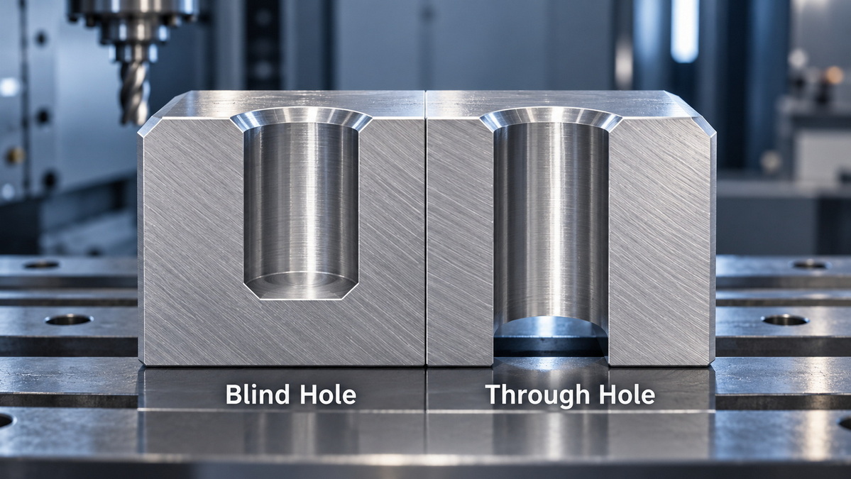
A blind hole is a machined hole that has a closed bottom and does not extend through the entire thickness of a workpiece. It is commonly produced by drilling, milling, boring, reaming, tapping, or thread milling.
Blind holes are frequently used when a part requires fastening, positioning, or internal assembly features without creating an opening on the opposite side. They are found in custom CNC-machined parts, injection mold components, stamping dies, tooling plates, machine frames, electronic housings, automotive parts, and industrial equipment.
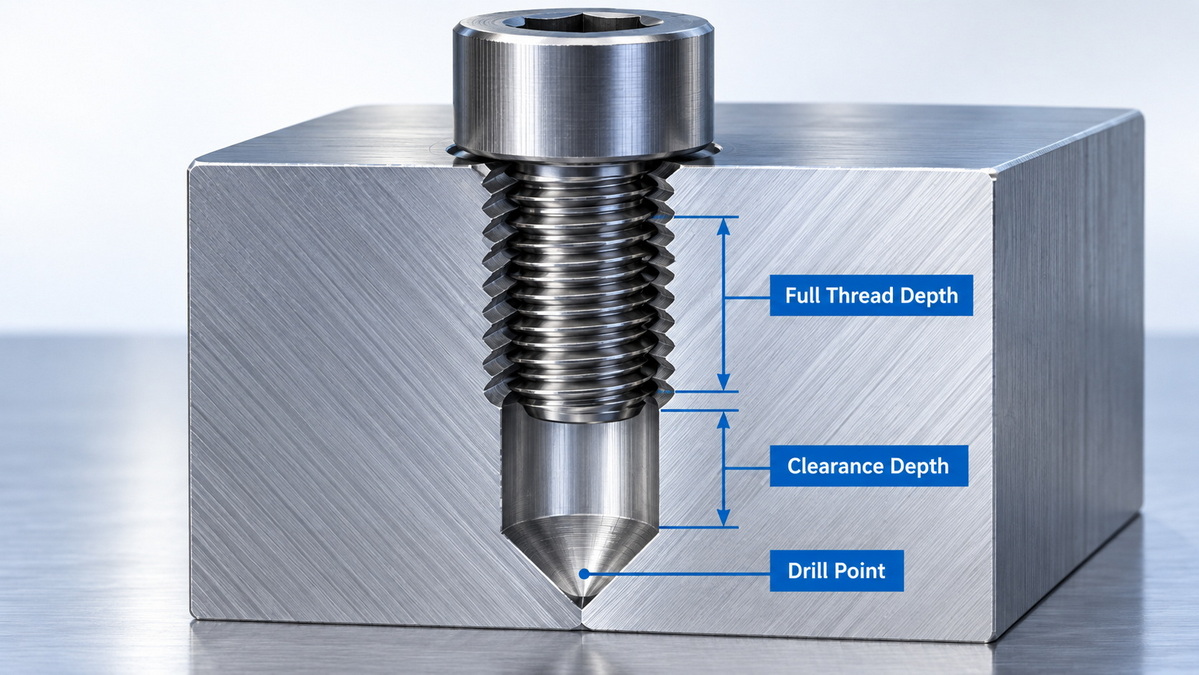
A typical blind hole has three important areas:
- Hole entrance: The opening where the drill, tap, screw, pin, or insert enters the part
- Functional depth: The usable portion of the hole needed for fastening, locating, sealing, or assembly
- Bottom clearance: The extra space below the functional area that accounts for the drill point, tap lead, screw tip, or debris
The closed bottom is what makes a blind hole different from a through hole. It also creates manufacturing challenges because chips, heat, and cutting forces must be controlled inside a confined space.
| Feature | Blind Hole | Through Hole |
|---|---|---|
| Hole structure | Stops at a specified depth | Passes through the complete workpiece |
| Bottom condition | Closed bottom | Open exit on the opposite side |
| Tool access | Usually available from one side | Often accessible from both sides |
| Chip evacuation | More difficult | Usually easier |
| Depth control | Highly important | Less critical |
| Typical applications | Concealed threads, internal fastening, fluid blocks, housings | Bolting, pins, pass-through wiring, fluid channels |
| Exterior appearance | Keeps the opposite surface intact | Creates an opening on both sides |
| Inspection requirement | Often requires depth verification | Usually easier to inspect visually |
Blind holes are not always the best choice. In many applications, a through hole is easier and more economical to machine. However, a blind hole is often necessary when a through hole would create a leak path, reduce strength, interfere with an internal feature, or damage the appearance of the finished product.
Blind holes support both engineering and aesthetic requirements. They allow manufacturers to create internal mounting points, retain material on visible surfaces, and package more functions into compact parts.
Many products need smooth and uninterrupted outer surfaces. This is especially important for consumer electronics, medical equipment, camera housings, premium appliances, automotive interior components, and industrial enclosures.
A blind threaded hole allows a screw to secure an internal bracket, cover, PCB, or subassembly without leaving a visible hole on the opposite face.
Blind holes are often used in hydraulic blocks, pneumatic manifolds, pump housings, valve bodies, pressure-retaining components, and sealed electronic enclosures.
A through hole can create a direct path for fluid, air, dust, moisture, or contaminants. A blind hole retains material at the bottom of the cavity and may help preserve sealing performance.
However, a blind hole must be designed with sufficient remaining wall thickness. If the hole is drilled too deep or is positioned too close to another cavity, the remaining material can become too thin and may weaken the part.
A through hole removes material across the entire thickness of a component. In load-bearing or thin-wall parts, this can reduce stiffness or create a stress concentration.
Blind holes allow engineers to add mounting points while keeping more material in the structure. This is useful for brackets, machine frames, mounting plates, robotic components, tooling bases, and automotive assemblies.
Some products cannot be accessed from both sides after assembly. Blind holes allow screws, dowels, threaded inserts, and locating pins to be installed from one accessible surface.
This is common in enclosed assemblies, compact mechanical systems, electrical cabinets, automation equipment, fixtures, and molded or machined housings.
Modern products often combine mechanical, electrical, thermal, and structural functions into smaller spaces. Blind holes help designers install components inside a housing without increasing the outside dimensions of the finished product.
Blind holes require more process control than through holes because the cutting tool enters a closed cavity. Chips cannot simply pass through the material. Heat can build up near the bottom of the hole, and the tool must stop at a precise depth.
Chip evacuation is one of the most important considerations in blind-hole drilling and tapping.
When a drill cuts into metal, plastic, or other materials, it produces chips. In a through hole, chips can often exit through the opposite side. In a blind hole, chips must travel back out through the drill flutes.
If chips are not removed effectively, they can:
- Pack at the bottom of the hole
- Scratch the hole wall
- Reduce surface finish quality
- Increase drilling force
- Cause drill breakage
- Produce inconsistent hole depth
- Interfere with tapping
- Create burrs or deformation near the entrance
Manufacturers may use peck drilling cycles to improve chip removal. During peck drilling, the tool periodically retracts from the hole so chips can clear before drilling continues.
For demanding blind-hole applications, the machining process may also include:
- Through-spindle coolant
- High-pressure coolant
- Optimized drill flute geometry
- Controlled drilling parameters
- Specialized deep-hole drills
- Compressed air for suitable materials
- Tool coatings selected for the workpiece material
- Custom chip-breaking toolpaths
Heat is another major challenge. A blind hole can trap chips near the cutting area, which increases friction and heat.
Excessive heat can cause:
- Faster tool wear
- Poor hole finish
- Work hardening in stainless steel
- Dimensional variation
- Discoloration in some materials
- Burr formation
- Part distortion
- Reduced thread quality
Material selection strongly affects the machining process. Aluminum usually allows high-speed drilling, while stainless steel, titanium, hardened steel, and nickel-based alloys require more controlled cutting conditions.
Blind-hole depth is often a functional dimension. A hole that is too shallow may prevent a screw, dowel pin, insert, spring, sensor, or mating component from seating correctly. A hole that is too deep may weaken the part, break through into another feature, or create an unacceptable thin wall.
The CNC machining program must account for more than the dimension shown on the drawing. It should consider:
- Drill-point angle
- Required full-diameter depth
- Required usable thread depth
- Tool wear
- Fixture stability
- Workpiece variation
- Chamfer depth
- Datum selection
- Safety clearance from nearby features
Blind threaded holes are particularly sensitive because a tap cannot create full threads immediately at the bottom of the hole.
Most cutting taps have a lead section. The lead section gradually forms threads before reaching full thread depth. Therefore, the total drilled depth must usually be deeper than the required usable thread depth.
For example, a drawing may require 12 mm of full thread engagement, but the drilled hole may need additional depth below the thread to accommodate the tap lead and the screw tip.
A drawing should clearly distinguish between:
- Drill depth
- Tap depth
- Full thread depth
- Minimum thread engagement
- Bottom clearance
Without this information, a part may pass a basic inspection but still fail during assembly.

Good blind-hole design reduces machining risk, shortens production time, and improves repeatability.
For threaded blind holes, it is important to specify the required full thread depth separately from the drill depth.
A useful drawing note may look like this:
> M6 × 1.0 thread, 12 mm minimum full thread depth, 16 mm minimum drill depth.
This note gives the machinist the functional requirement while allowing sufficient clearance for the drill point and tap lead.
Standard twist drills create a conical point at the bottom of the hole. This means the entire nominal depth is not available as a full-diameter cylindrical section.
If a component must sit flat at the bottom of the hole, the design may require:
- A flat-bottom pocket
- End milling after drilling
- A custom flat-bottom drill
- A counterbore
- Additional clearance below the functional depth
- A specially designed tool for high-volume production
A standard drilled blind hole should not be assumed to have a flat bottom.
Blind-hole difficulty increases when the hole becomes deep relative to its diameter.
For example, a hole that is 30 mm deep and 5 mm in diameter has a depth-to-diameter ratio of 6.
As the ratio increases, chip evacuation becomes more difficult, tool rigidity decreases, and the possibility of drill deflection or breakage increases.
Deep, small-diameter holes may require:
- Specialized drilling tools
- Reduced feed rates
- Advanced coolant delivery
- Peck drilling cycles
- Pilot-hole strategies
- Additional inspection
- Longer machining cycles
When possible, designers should avoid specifying deep blind holes with very small diameters unless the function of the part truly requires them.
Blind holes require access for drilling, tapping, deburring, inspection, and sometimes reaming or boring.
Before releasing a design, confirm the following:
- The hole is accessible from the machining direction
- A drill or tap can approach the hole without collision
- Nearby walls do not block the toolholder
- Internal ribs and pockets do not interfere with tool movement
- The part can be held securely during machining
- The hole can be measured after machining
- There is enough space for a chamfer or deburring tool
Poor tool access can force the use of long-reach tooling, special fixtures, multi-axis machining, or additional setups. These requirements increase cost and can reduce production efficiency.
A small chamfer at the hole entrance can improve assembly and reduce burrs. It helps guide screws, pins, inserts, and fasteners into the hole.
An entrance chamfer can also protect the edge from damage during handling or repeated assembly.
However, the chamfer should not be oversized. A large chamfer may reduce usable thread engagement near the surface or weaken a thin wall around the hole.
The correct process depends on the required geometry, material, tolerance, surface finish, depth, production quantity, and end-use function.
| Process | Best Use | Main Benefit | Key Consideration |
|---|---|---|---|
| CNC drilling | Standard round blind holes | Fast and cost-effective | Usually leaves a conical bottom |
| Peck drilling | Deep holes or difficult materials | Improves chip evacuation | Increases cycle time |
| End milling | Flat-bottom holes and pockets | Creates flat-bottom geometry | Less efficient for small holes |
| Boring | High-precision diameters | Improves size and concentricity | Slower than standard drilling |
| Reaming | Fine surface finish and accurate diameter | Produces tighter final dimensions | Requires a stable pre-drilled hole |
| Spiral-flute tapping | Blind threaded holes | Helps pull chips upward | Requires proper lubrication and clearance |
| Form tapping | Ductile materials | Produces threads without cutting chips | Requires correct pilot-hole size |
| Thread milling | Large or high-value threaded holes | Flexible depth and thread control | Can be slower for small high-volume holes |
CNC drilling is the most common method for producing blind holes. It is suitable for many materials and part types, including aluminum, steel, stainless steel, brass, copper, plastics, and engineering alloys.
The process can be highly efficient when the hole is not excessively deep and the material allows stable chip formation.
Peck drilling is commonly used when chips need additional help leaving the hole. The drill advances into the material, retracts to clear chips, and then continues drilling.
This method is useful for deep holes, sticky materials, long-chip materials, and applications where tool breakage risk is higher.
End milling is often selected when a flat-bottom blind hole is required. It is also useful for larger pockets, non-round cavities, or holes with a controlled bottom surface.
Because an end mill can create a flatter floor than a standard drill, it is often used for seating surfaces, insert pockets, countersinks, and internal assembly features.
Blind holes can be threaded using cutting taps, form taps, or thread mills.
Spiral-flute taps are commonly used for blind holes because their flute design helps move chips upward and out of the hole.
Form taps are useful in suitable ductile materials because they form threads by displacing material rather than cutting chips. This can reduce chip-related problems, but the pilot-hole diameter, lubrication, and material properties must be carefully controlled.
Thread milling is often selected for larger threads, expensive materials, high-value components, or applications where close control of thread depth is required.
Reliable blind-hole production begins before the machine starts cutting. The best results come from reviewing the part as a complete manufacturing system.
The first question is not simply, "What is the hole diameter?"
The more important questions are:
- What will be installed in the hole?
- Is the hole threaded?
- What is the required engagement depth?
- Does the bottom need to be flat?
- Will the hole hold pressure, fluid, or a sealing component?
- Is the hole located near a thin wall?
- Is the hole cosmetic, structural, or assembly-critical?
- What tolerance and inspection method are required?
Understanding the function helps determine the most appropriate process.
Material affects cutting speed, feed, coolant choice, tool geometry, chip shape, and tapping method.
For example, aluminum may produce manageable chips at higher cutting speeds, while stainless steel may work harden if machining parameters are incorrect. Titanium and nickel alloys can generate high heat and require more conservative process control.
Geometry is equally important. A hole close to a corner, thin wall, curved surface, internal cavity, or intersecting feature may require a special machining strategy.
The machining team selects drilling tools, tapping tools, cutting fluids, speeds, feeds, and chip-control strategies based on the part requirements.
The right tool selection can improve:
- Hole straightness
- Surface finish
- Tool life
- Thread consistency
- Cycle time
- Dimensional stability
- Production repeatability
Depth control includes more than setting a CNC Z-axis value. The process must account for tool length offsets, drill-point geometry, machine repeatability, fixture location, and workpiece variation.
For critical parts, depth may be verified during first-article inspection and monitored during production.
The inspection method should match the importance of the hole.
Possible inspection methods include:
- Digital depth gauges
- Thread plug gauges
- Pin gauges
- Bore gauges
- Coordinate measuring machines
- Optical measurement systems
- Borescopes
- Assembly test fixtures
A blind threaded hole should be checked not only for thread presence, but also for usable thread depth and bottom clearance.
Common causes:
- Chips trapped at the hole bottom
- Excessive feed rate
- Incorrect cutting speed
- Insufficient lubrication
- Poor tool alignment
- Worn cutting tools
- Inadequate pilot-hole size
- Insufficient clearance below the thread
Prevention methods:
- Use the correct tool for the material
- Apply suitable coolant or lubrication
- Control peck drilling cycles
- Maintain sharp tooling
- Verify pilot-hole dimensions
- Allow sufficient bottom clearance
- Use stable fixturing
- Monitor tool wear during production
Common causes:
- Drill depth is confused with thread depth
- Tap lead is not considered
- Thread depth is not specified clearly
- A bottoming tap is used incorrectly
- Chip accumulation blocks the tap
Prevention methods:
- Specify minimum full thread depth
- Provide additional drill depth
- Select an appropriate tap style
- Use thread milling where necessary
- Verify thread quality with suitable gauges
Common causes:
- The screw is longer than the usable hole depth
- The hole lacks bottom clearance
- The screw tip is not included in the assembly calculation
- A washer, gasket, or bracket thickness is overlooked
Prevention methods:
- Check the complete assembly stack-up
- Confirm screw length and thread engagement
- Allow clearance below the screw tip
- Verify the assembly during prototype validation
Common causes:
- Chip recutting
- Excess heat
- Dull tooling
- Unstable workholding
- Incorrect cutting parameters
- Poor coolant delivery
Prevention methods:
- Improve chip evacuation
- Use appropriate coolant
- Adjust cutting speed and feed
- Use suitable tool coatings
- Stabilize the part during machining
- Replace worn tools before quality declines
Common causes:
- Incorrect depth programming
- Inaccurate setup
- Insufficient wall thickness
- Part variation
- Poor datum selection
Prevention methods:
- Define safe wall thickness requirements
- Review hole depth against nearby features
- Use reliable fixture datums
- Verify first-article dimensions
- Add inspection controls for critical locations
Blind holes are used in a wide range of industries because they support compact assemblies, concealed fastening, and precise mechanical location.
Blind holes are used in brackets, sensor housings, engine covers, transmission components, interior assemblies, fixtures, and EV battery-related structures.
Aerospace manufacturers use blind holes in lightweight brackets, avionics housings, structural fittings, interior systems, and precision assembly fixtures.
Medical equipment and device manufacturers use blind holes in instrument bodies, diagnostic housings, surgical assemblies, laboratory equipment, and precision mounting features.
Blind holes are common in aluminum housings, heat sinks, PCB mounting plates, control boxes, robot components, sensor mounts, and automation fixtures.
Industrial applications include hydraulic manifolds, pump bodies, valve blocks, machine bases, jigs, fixtures, tooling plates, mold components, and custom machine parts.
Blind holes help create cleaner product designs in camera bodies, appliances, smart devices, handheld tools, premium metal housings, and engineered consumer products.

Blind holes are essential features in custom precision machining, but they require more attention than standard through holes. Their closed-bottom geometry creates additional challenges in chip evacuation, heat control, drilling depth, tapping, inspection, and assembly fit.
The most effective blind-hole designs clearly define the required functional depth, usable thread engagement, drill depth, bottom condition, wall thickness, and inspection requirements. Designers should also consider tool access, material properties, depth-to-diameter ratio, chip-control needs, and the final assembly condition.
When blind holes are planned correctly, they can deliver clean exterior surfaces, compact assemblies, secure fastening, improved structural continuity, and reliable product performance. When they are poorly specified, they can create avoidable production delays, assembly failures, and machining costs.
U-Need supports global brands, distributors, and manufacturers with custom precision parts machining, mold manufacturing, sheet metal fabrication, and manufacturing-focused engineering support. From prototypes to production parts, the right machining strategy helps turn complex blind-hole requirements into stable, repeatable, and high-quality components.
A blind hole is a hole that stops at a specified depth inside a workpiece. Unlike a through hole, it does not pass through the opposite side of the material.
A blind hole has a closed bottom and must be machined to a controlled depth. A through hole passes completely through the part and has an open exit on the opposite side.
Yes. Blind holes can be threaded using cutting taps, spiral-flute taps, form taps, or thread mills. The design must provide enough depth for the required usable thread engagement and bottom clearance.
Blind holes are more difficult because chips and heat can become trapped inside the hole. They also require precise depth control and may need special drilling, tapping, coolant, and inspection methods.
The required extra depth depends on thread size, tap style, screw geometry, material, and assembly requirements. The drawing should specify the minimum full thread depth separately from the minimum drill depth.
Yes. A flat-bottom blind hole can be produced by end milling, flat-bottom drilling, counterboring, or specialized cutting tools. Standard twist drills normally create a conical bottom.
Taps can break because of trapped chips, insufficient lubrication, incorrect pilot-hole size, excessive cutting force, poor alignment, worn tooling, or insufficient bottom clearance.
They can be more expensive because they require controlled depth, more careful chip evacuation, possible special tapping methods, and additional inspection. The actual cost depends on material, tolerance, depth, diameter, and production volume.
Stainless steel, titanium, hardened steel, nickel alloys, and long-chipping materials can be more challenging. These materials may require specialized tooling, controlled cutting parameters, and improved coolant delivery.
1. TOPS Precision. "[The Engineer's Guide to Blind Holes in Machining]."
2. Machining Doctor. "[Blind Hole in Machining: Definition & Tapping Tips]."
3. Harvey Performance Company, In The Loupe. "[Holemaking]."
4. Harvey Performance Company, In The Loupe. "[Titan USA Archives]."
5. Harvey Performance Company, In The Loupe. "[Tool Information Guides]."
6. Harvey Performance Company, In The Loupe. "[Milling]."


