Views: 287 Author: U-Need Publish Time: 2026-10-02 Origin: Site
Content Menu
>> Key PEEK Material Characteristics
● Why Is PEEK Difficult to Machine?
● Where Are Machined PEEK Parts Used?
>> Medical and Healthcare Equipment
>> Semiconductor Manufacturing
● Selecting the Right PEEK Grade
>> Virgin PEEK
● Why Annealing Matters for Machined PEEK
>> Typical Precision Machining Sequence
● CNC Machining Methods for PEEK Parts
>> CNC Milling for Complex PEEK Components
>> CNC Turning for Cylindrical PEEK Parts
>> Drilling, Reaming, and Tapping
● Design Guidelines for Machined PEEK Parts
>> Recommended Design Practices
>> Functional Tolerancing Reduces Total Cost
● Common PEEK Machining Problems
>> Melted Edges or Burr Formation
>> Deep-Hole Cracking or Distortion
● Precision Manufacturing Support for PEEK Projects
● Summary
>> What tolerance can be achieved in PEEK machining?
>> Does PEEK require annealing before machining?
>> Is virgin PEEK better than carbon-filled PEEK?
>> What information is needed for a PEEK machining project?
PEEK machining is one of the most reliable methods for producing high-performance plastic parts used in demanding medical, aerospace, semiconductor, oil and gas, automotive, and industrial environments. Yet achieving stable dimensions, clean surface finishes, and repeatable quality requires more than standard CNC programming.
Heat control, residual-stress management, material selection, fixturing, tool condition, and inspection discipline all influence the final performance of a machined PEEK component. For global brands, distributors, and manufacturers, working with an experienced precision manufacturing partner can reduce development risk and improve consistency from prototype through repeat production.
U-Need provides end-to-end precision manufacturing solutions in China, including custom precision parts machining, mold manufacturing, injection molds, stamping dies, cold-forging dies, laser cutting, bending, stamping, and sheet metal fabrication. For PEEK projects, the objective is not simply to remove material. It is to create parts that are functional, stable, manufacturable, and aligned with the requirements of their final application.
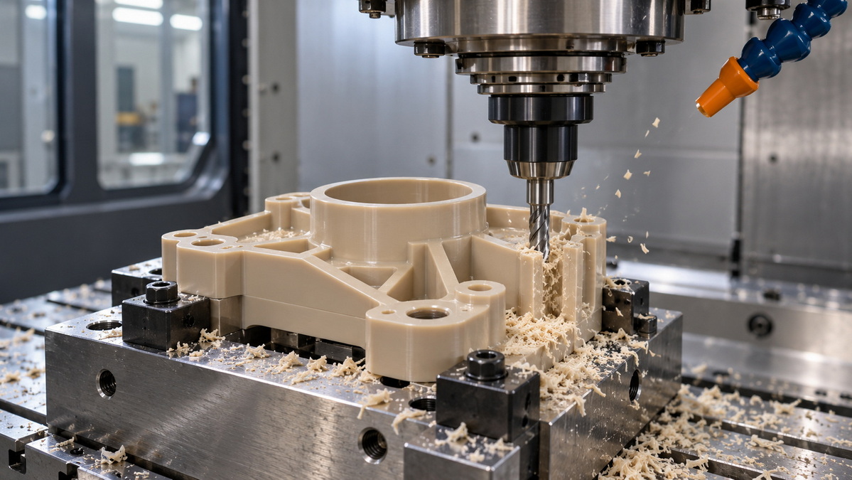
PEEK stands for polyether ether ketone. It is a semi-crystalline, high-performance thermoplastic widely used when standard plastics cannot meet the required temperature resistance, chemical resistance, mechanical strength, wear performance, or electrical insulation requirements.
PEEK is frequently selected for applications exposed to high temperatures, aggressive chemicals, repeated sterilization, mechanical loading, pressure, friction, and electrical stress. It is valued for maintaining useful performance in environments where materials such as ABS, nylon, polycarbonate, or acetal may not be suitable.
The material offers a strong balance of thermal performance, chemical resistance, mechanical stability, and low moisture absorption. These advantages make it suitable for many critical applications, but they also make it more demanding to machine accurately.
| Property | Typical Value or Characteristic | Manufacturing Importance |
|---|---|---|
| Continuous-use temperature | Up to approximately 260°C | Suitable for demanding thermal environments |
| Glass-transition temperature | Approximately 143°C | Local heat can reduce stiffness and cause dimensional movement |
| Melting temperature | Approximately 343°C | Indicates high thermal capability |
| Tensile strength | Approximately 90–100 MPa | Supports structural and functional component designs |
| Density | Approximately 1.30 g/cm³ | Supports lightweight part design |
| Moisture absorption | Low | Helps improve dimensional stability in humid environments |
| Chemical resistance | Excellent against many chemicals | Useful for chemical processing and fluid-handling systems |
| Electrical properties | Strong insulation capability | Suitable for electrical and electronic components |
Actual values vary depending on the specific grade, reinforcement, stock form, crystallinity, processing history, and operating environment.
PEEK can be machined using CNC milling, CNC turning, drilling, reaming, tapping, and other common precision manufacturing methods. However, it does not behave like aluminum, stainless steel, brass, or carbon steel during cutting.
The biggest challenge is heat management.
PEEK has lower thermal conductivity than metals. Heat created by cutting may remain concentrated around the tool edge and workpiece instead of quickly dispersing through the part. If the tool is dull, the cutting speed is poorly controlled, the feed is too light, or chips are not removed effectively, the material may soften or deform locally.
This can result in:
- Melted or smeared surfaces.
- Burrs around holes and edges.
- Dimensional variation.
- Poor surface finish.
- Hole deformation.
- Local discoloration.
- Residual stress.
- Warpage after machining.
- Unstable tolerances after assembly or thermal exposure.
A PEEK part may measure correctly immediately after machining but move later if internal stress is released. This is why stable PEEK machining depends on a controlled process rather than a single cutting operation.
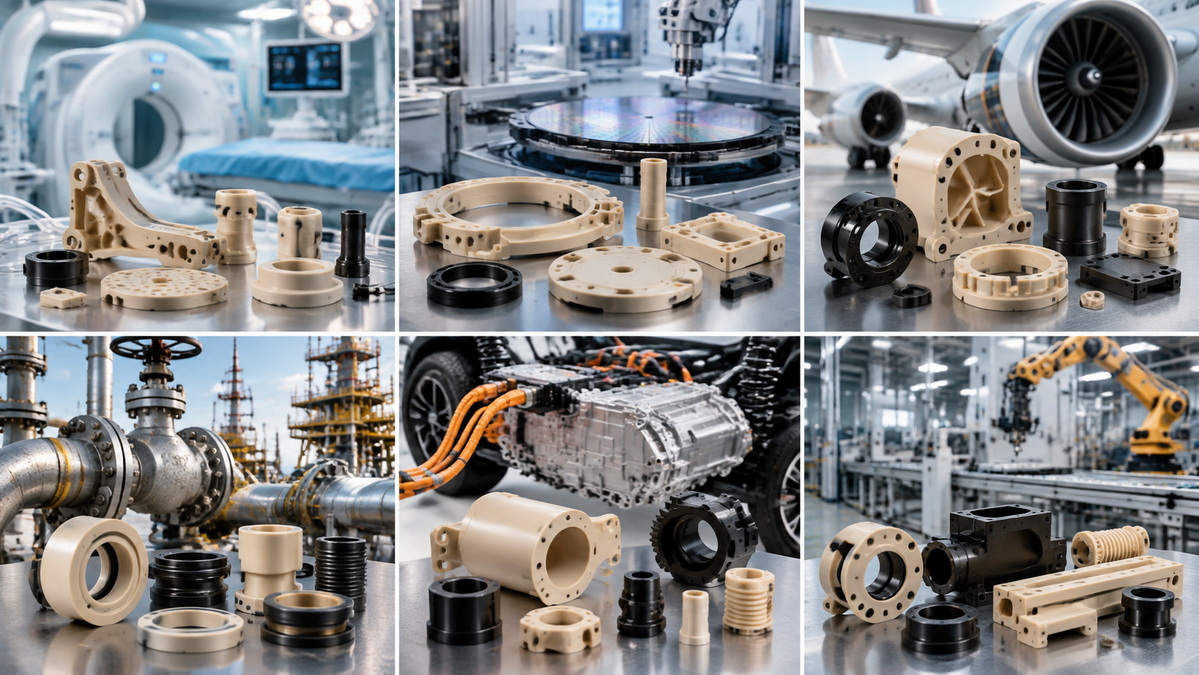
Machined PEEK parts are commonly used where performance, reliability, cleanliness, and long service life are more important than low material cost.
PEEK is often used for medical-device components, diagnostic equipment parts, surgical instrument elements, sterilizable fixtures, laboratory components, and specialized tooling.
Its low moisture absorption, chemical resistance, and ability to withstand repeated sterilization make it useful in demanding healthcare environments.
The semiconductor industry often requires materials with high purity, dimensional stability, chemical resistance, and electrical insulation properties.
Machined PEEK parts may be used in wafer-handling systems, test fixtures, electrical insulating components, semiconductor processing equipment, and precision positioning assemblies.
Aerospace applications may use PEEK to reduce weight while maintaining performance under temperature changes, vibration, fluid exposure, and mechanical load.
Typical examples include cable-management components, brackets, insulation parts, seals, connectors, bushings, and lightweight structural elements.
PEEK is suitable for many oil and gas applications because it can resist chemicals, elevated temperatures, pressure, wear, and harsh operating conditions.
Examples include seal rings, backup rings, valve seats, electrical connectors, insulating components, wear rings, and downhole equipment parts.
Machined PEEK is increasingly considered for high-temperature automotive and electric vehicle applications. It can be used in electrical insulation systems, battery-related components, transmission elements, fluid systems, and high-performance sensor housings.
Industrial equipment manufacturers use PEEK for components exposed to friction, temperature, chemicals, and repeated motion.
Common industrial parts include:
- Bushings.
- Wear pads.
- Bearing cages.
- Rollers.
- Gears.
- Valve components.
- Pump components.
- Electrical insulators.
- Sealing elements.
- Precision spacers.
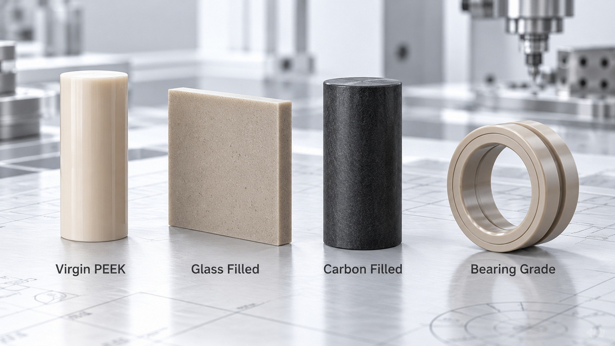
Material selection is one of the most important decisions in any PEEK project. The best grade depends on the component's working temperature, load, friction, chemical exposure, electrical requirements, cleanliness standard, regulatory needs, and dimensional tolerance.
Virgin PEEK is unfilled PEEK without glass fiber, carbon fiber, PTFE, graphite, or similar additives. It is commonly used when electrical insulation, chemical resistance, cleanliness, toughness, and low contamination are especially important.
Virgin PEEK is often suitable for:
- Electrical insulators.
- Medical-device components.
- Semiconductor fixtures.
- Chemical-processing parts.
- Fluid-control components.
- Precision housings.
- Structural polymer parts.
Virgin PEEK is generally easier to machine than heavily reinforced PEEK grades. However, it may show greater thermal expansion than fiber-filled grades, particularly when exposed to changing temperatures.
Glass-filled PEEK generally offers improved stiffness and dimensional stability compared with virgin PEEK. It can be a practical choice for structural parts that need better rigidity at elevated temperatures.
This grade may be used for:
- High-temperature industrial fixtures.
- Structural supports.
- Machine components.
- Thermal insulation parts.
- Precision mechanical assemblies.
Glass fiber can increase tool wear. Cutting-tool selection and process control should account for its abrasive nature.
Carbon-fiber-filled PEEK generally provides high stiffness, lower thermal expansion, improved wear behavior, and strong structural performance. It is often selected for demanding industrial, aerospace, and wear-related applications.
Typical uses include:
- Wear rings.
- Bearings.
- Structural brackets.
- High-load bushings.
- Aerospace components.
- Mechanical support parts.
- High-performance machine elements.
Carbon-filled PEEK is more abrasive than virgin material and may require careful machining strategies. It may also not be appropriate where electrical insulation is required.
Bearing-grade PEEK may contain additives such as PTFE, graphite, and carbon fiber. These additives are used to improve friction and wear properties in sliding or rotating applications.
Bearing-grade PEEK is often considered for:
- Bushings.
- Sliding guides.
- Wear pads.
- Dry-running bearings.
- Roller components.
- Pump parts.
- Mechanical seals.
The final material selection should always reflect the actual operating conditions rather than relying on a general material description.
Annealing is often essential for high-precision PEEK components.
Internal stress can be introduced during material production, cutting of stock shapes, rough machining, clamping, and uneven material removal. If these stresses are not properly managed, the part may shift after machining or during use.
This is especially important for components with:
- Tight dimensional tolerances.
- Deep pockets.
- Thin walls.
- Long bores.
- Uneven wall thickness.
- Large material-removal volumes.
- Flatness requirements.
- Precision sealing surfaces.
- Critical hole locations.
- Exposure to elevated temperatures.
A controlled annealing process can reduce residual stress and improve dimensional stability. The exact temperature profile and cycle time depend on the PEEK grade, stock thickness, shape complexity, and final performance requirements.
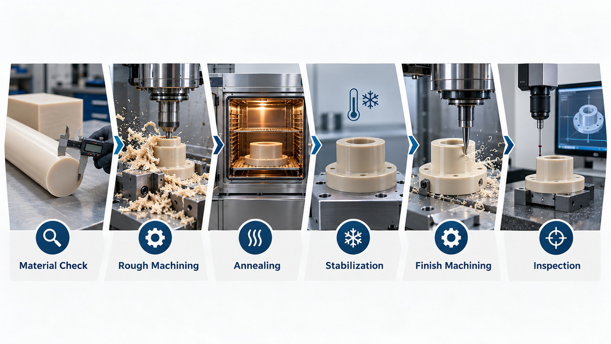
A robust process for tight-tolerance PEEK components often includes the following stages:
1. Material verification
Confirm the required grade, stock form, color, certification needs, and any application-specific requirements.
2. Rough machining
Remove the majority of excess material while leaving suitable machining allowance for critical surfaces.
3. Stress-relief annealing
Heat and cool the part gradually under controlled conditions to reduce internal stress.
4. Stabilization period
Allow the part to return to a stable, controlled ambient condition before final machining.
5. Finish machining
Produce final dimensions on critical bores, sealing faces, threads, datum features, flatness surfaces, and external profiles.
6. Final inspection
Verify critical dimensions, geometric tolerances, surface finish, and visual quality under suitable measurement conditions.
The best machining method depends on the part geometry, volume, tolerance, grade, and functional requirements.
CNC milling is used for PEEK housings, brackets, manifolds, plates, fixtures, structural components, medical parts, and complex three-dimensional shapes.
Good milling results depend on sharp cutting tools, balanced toolpaths, stable fixturing, and effective heat management.
Important milling practices include:
- Use sharp and polished cutting edges.
- Maintain a proper chip load to avoid tool rubbing.
- Avoid long tool dwell at corners and pocket bottoms.
- Remove material in stages for deep pockets.
- Support thin walls and flexible features.
- Use efficient chip evacuation.
- Select coolant or air-blast methods appropriate for the material and application.
- Avoid excessive clamping pressure that may deform the part.
CNC turning is commonly used for PEEK rings, bushings, spacers, seal seats, threaded fittings, valve components, cylindrical insulators, and bearing-related components.
Because PEEK is less rigid than metal, workholding should be carefully controlled. Excessive chuck pressure can deform the workpiece, while insufficient clamping can create vibration and poor surface finish.
Useful workholding methods include:
- Collets.
- Soft jaws.
- Expanding mandrels.
- Custom fixtures.
- Vacuum fixtures for suitable flat components.
- Support centers for long turned parts.
Drilling and hole finishing require careful control because chips can trap heat inside a deep hole. This may create poor surface quality, hole distortion, cracking risk, or dimensional instability.
For critical holes:
- Use sharp drills with suitable geometry.
- Apply peck-drilling cycles when necessary.
- Clear chips effectively.
- Avoid excessive feed force.
- Drill undersize when reaming or boring is required.
- Finish critical bores after stabilization.
- Inspect holes at a controlled temperature.
- Use thread designs that match wall thickness and load conditions.
There is no single tolerance capability that applies to every PEEK part. Achievable tolerances depend on geometry, stock condition, material grade, part size, wall thickness, fixture design, machining strategy, thermal stability, inspection conditions, and whether annealing is included.
| Tolerance Category | Typical Range | Suitable Part Types |
|---|---|---|
| General machining | ±0.10 mm | Covers, guards, brackets, noncritical industrial components |
| Precision machining | ±0.05 mm | Bushings, connectors, valve components, precision housings |
| High-precision machining | ±0.025 mm | Semiconductor fixtures, sealing parts, medical assemblies |
| Critical functional features | ±0.01–0.02 mm | Precision bores, aerospace interfaces, specialized medical or semiconductor parts |
These ranges should be reviewed alongside the specific drawing and functional requirements. A critical bore may need a much tighter tolerance than an external profile. Applying unnecessary tight tolerances across all dimensions can increase cost, machining time, inspection effort, and scrap risk.
Part design has a direct influence on machining quality, lead time, unit cost, and long-term dimensional stability.
The most effective drawings clearly identify functional dimensions, critical tolerances, datums, surface-finish requirements, and application conditions.
| Design Feature | Recommended Approach | Manufacturing Benefit |
|---|---|---|
| Internal corners | Add practical corner radii | Improves tool access and reduces machining time |
| Thin walls | Keep thickness as uniform as possible | Reduces distortion and vibration |
| Deep pockets | Avoid extreme depth-to-width ratios | Improves rigidity and chip evacuation |
| Tight tolerances | Apply only to functional dimensions | Controls cost and reduces unnecessary risk |
| Threads | Use standard sizes where possible | Simplifies tooling and inspection |
| Datums | Define functional datum surfaces clearly | Supports consistent fixturing and measurement |
| Surface finish | Specify only where performance requires it | Avoids unnecessary polishing or fine machining |
| Material grade | Define the exact grade and approved equivalent | Helps control performance and traceability |
One common design issue is applying a very tight tolerance to every dimension on a drawing. This may make the part more expensive without improving its actual function.
For example, a precision locating bore may require a tolerance of ±0.02 mm because it mates with a pin or shaft. The external profile of the same component may function properly with a tolerance of ±0.10 mm.
Assigning the tight tolerance only to the locating feature allows the manufacturer to focus machining and inspection resources where they create actual value.
This approach can improve:
- Manufacturing efficiency.
- Lead time.
- Inspection consistency.
- Production yield.
- Cost control.
- Long-term scalability.
Understanding common issues helps engineers create more reliable designs and choose the right process route.
Common causes:
- Internal material stress.
- Aggressive material removal.
- Uneven wall thickness.
- Poor machining sequence.
- Inadequate stabilization.
- Unbalanced geometry.
Practical prevention:
- Use staged machining.
- Leave finish allowance after roughing.
- Remove material evenly from both sides where possible.
- Use controlled annealing for critical parts.
- Avoid excessive clamping force.
- Finish-machine stable datum surfaces after stress relief.
Common causes:
- Dull cutting tools.
- Excessive heat.
- Vibration.
- Incorrect feed rate.
- Poor chip evacuation.
- Inadequate workholding.
Practical prevention:
- Use sharp tools.
- Maintain appropriate chip load.
- Improve fixture rigidity.
- Avoid excessive tool dwell.
- Manage chips and cutting heat.
- Use suitable finishing passes.
Common causes:
- Tool rubbing instead of cutting.
- Low chip load.
- Excessive cutting heat.
- Incorrect tool geometry.
- Inadequate chip removal.
Practical prevention:
- Use polished, sharp cutting tools.
- Adjust feed and speed.
- Apply suitable air or coolant support.
- Avoid overly light finishing passes.
- Deburr carefully without damaging critical surfaces.
Common causes:
- Heat accumulation.
- Drill deflection.
- Part movement during machining.
- Material stress release.
- Measurement at uncontrolled temperature.
Practical prevention:
- Drill undersize before reaming or boring.
- Use peck-drilling where appropriate.
- Ensure stable fixturing.
- Finish critical holes after stabilization.
- Inspect in consistent environmental conditions.
Common causes:
- Poor chip evacuation.
- Excessive heat.
- High drilling force.
- Residual stress in thick stock.
- Inadequate process control.
Practical prevention:
- Use progressive drilling cycles.
- Clear chips frequently.
- Reduce excessive thrust.
- Select suitable drill geometry.
- Consider annealing for critical thick-section components.
PEEK parts often require more engineering attention than standard plastic components. A reliable manufacturing process begins with a careful review of the drawing, grade, function, tolerance requirements, and expected production volume.
U-Need supports custom PEEK machining projects with a focus on manufacturability, dimensional stability, and consistent production quality.
Manufacturing support may include:
- Design-for-manufacturability review for tolerance, wall thickness, tool access, threads, and machining sequence.
- Material-grade evaluation for virgin PEEK, glass-filled PEEK, carbon-filled PEEK, bearing-grade PEEK, and application-specific materials.
- CNC milling and turning for prototype, low-volume, and repeat-production parts.
- Stress-management planning for precision components with tight tolerances or high material-removal requirements.
- Custom fixture design for complex geometries and repeatable workholding.
- Inspection planning for critical dimensions, flatness, concentricity, surface finish, and geometric tolerances.
- Integrated manufacturing coordination for projects that also need metal inserts, injection molds, stamping dies, laser-cut brackets, bent sheet metal parts, or precision metal components.
- Export-oriented project management for global OEMs, distributors, industrial brands, and product-development teams.
Machining PEEK successfully requires a balance of material knowledge, machining capability, thermal control, stable fixturing, and disciplined inspection. The material can deliver excellent performance in demanding environments, but its dimensional behavior must be carefully managed from raw stock selection through final verification.
The most reliable results come from selecting the right PEEK grade, applying tolerances according to real functional needs, controlling residual stress, using sharp and suitable cutting tools, and planning the machining process around the geometry of the part.
For high-temperature, chemical-resistant, wear-resistant, electrically insulating, or tight-tolerance components, a well-planned PEEK machining process can provide durable and repeatable production results.
Share your 2D drawing, 3D CAD model, material requirement, annual quantity, critical tolerances, surface-finish requirements, and application details with U-Need for a practical manufacturing review.
Yes. PEEK can be processed using CNC milling, CNC turning, drilling, reaming, tapping, and other precision machining methods. Successful results depend on proper heat management, sharp cutting tools, stable workholding, chip evacuation, and stress control.
General PEEK components may be produced at approximately ±0.10 mm. Precision components can often achieve ±0.05 mm or ±0.025 mm with suitable process control. Critical features may reach approximately ±0.01–0.02 mm when the material, machining sequence, annealing strategy, fixture design, and inspection conditions are carefully controlled.
Not every PEEK part requires annealing. However, annealing is often recommended for thick stock, large material-removal projects, tight-tolerance components, thin-wall structures, deep-hole parts, and components exposed to elevated operating temperatures.
The answer depends on the application. Virgin PEEK is often preferred for electrical insulation, chemical resistance, low-contamination environments, and medical or semiconductor components. Carbon-filled PEEK is often selected for higher stiffness, improved wear performance, and lower thermal expansion in structural or friction-related applications.
In some applications, yes. PEEK can replace metal when lower weight, corrosion resistance, chemical resistance, electrical insulation, reduced friction, or high-temperature performance is required. However, engineers should evaluate mechanical load, stiffness, creep, fastening method, thermal expansion, safety requirements, and long-term service conditions before replacing a metal part.
A complete project package should include a 2D drawing, 3D CAD model, material grade, annual quantity, tolerance requirements, surface-finish requirements, color requirements, inspection requirements, functional application details, and any material traceability or compliance requirements.
1. Victrex. "PEEK Material Properties Guide."
[https://www.victrex.com/en/material-properties]
2. Victrex. "VICTREX 450G Polymer Datasheet."
[https://www.victrex.com/en/downloads/datasheets/victrex-peek-450g]
3. Victrex. "What Is Polyetheretherketone (PEEK) Polymer?"
[https://www.victrex.com/en/blog/2017/a-closer-peek-at-peek]
4. Ensinger. "Engineering Plastics: The Manual."
[https://www.ensinger-pc.com/wp-content/uploads/2022/04/Ensinger-Manual.pdf]
5. Ensinger Specialty Polymers. "Compression Molded PEEK."
[https://www.ensingerspi.com/guidelines-peek.cfm]
6. PEEKCHINA. "Mastering PEEK Machining: Essential Guidelines."
[https://www.peekchina.com/blog/peek-machining-guidelines.html]


