Views: 254 Author: U-Need Publish Time: 2026-11-22 Origin: Site
Content Menu
● CNC Machining vs 3D Printing: A Functional Testing Comparison
● When a CNC Machined Prototype Is Better
>> Tight Tolerances, Sealing Surfaces, and Mechanical Fits
>> Material Behavior Under Load, Heat, and Repeated Use
● When a 3D Printed Prototype Is Better
>> Fast Design Iteration and Assembly Checks
>> Complex Internal Geometry and Process-Specific Testing
● A Five-Step Plan for Reliable Prototype Testing
● Example: How to Validate a Housing Before Committing to a Mold
● Prototype Cost and Lead Time: Compare the Cost of Getting an Answer
● Request a Prototype Quote Built Around Your Test
>> Can a 3D printed prototype be used for functional testing?
>> Is CNC machining more accurate than 3D printing?
>> Which prototype should I use for snap-fit testing?
>> Can I machine a prototype after 3D printing it?
>> Can a CNC machined plastic prototype replace a molded sample?
Choose a CNC machining prototype when the test depends on a tight fit, a finished contact surface, or the behavior of a specific stock material. Choose a 3D printed prototype when you need to compare designs quickly, check assembly access, or test geometry that a cutting tool cannot reach. When the final part will be molded, stamped, or printed, neither prototype automatically qualifies it for production. The deciding factor is whether the prototype reproduces what could make the final part fail.
That distinction matters more than whether a prototype looks finished. A printed housing can tell you whether a technician can reach a connector. It may tell you little about how a molded latch holds up after repeated use. Likewise, a machined housing can validate the position of a seal groove without proving that a molded housing will stay flat enough to seal.
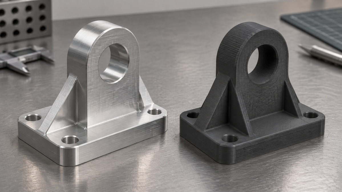
Functional testing checks whether a part does its job under defined conditions. That job could be as simple as letting a cable pass through an opening or as demanding as maintaining alignment under repeated loads. Identify the behavior you need to measure before choosing how to make the sample.
| Test objective | Better starting point | What to verify |
|---|---|---|
| Packaging, clearances, and tool access | 3D printing | That printing distortion does not affect the clearance you are checking |
| Bearing fit, alignment, and precision threads | CNC machining | The actual dimensions and locations of mating features |
| Load or deflection in a stock-metal bracket | CNC machining in the specified alloy and condition | Load direction, mounting conditions, and permanent deformation |
| Early snap-fit geometry | An engineering polymer print, such as SLS nylon | Engagement and access; do not assume the final latch will last as long |
| Flow through a curved internal passage | 3D printing | Whether the passage is clear and its dimensions and finish are representative enough |
| Warpage or durability in a molded housing | Prototype injection molding | Whether the material, tooling, and molding conditions represent the intended process |
The best choice can differ across features on the same part. If a complex printed body needs one accurate mounting bore, printing the body and machining the bore may answer the test question better than making the whole part by either process alone.
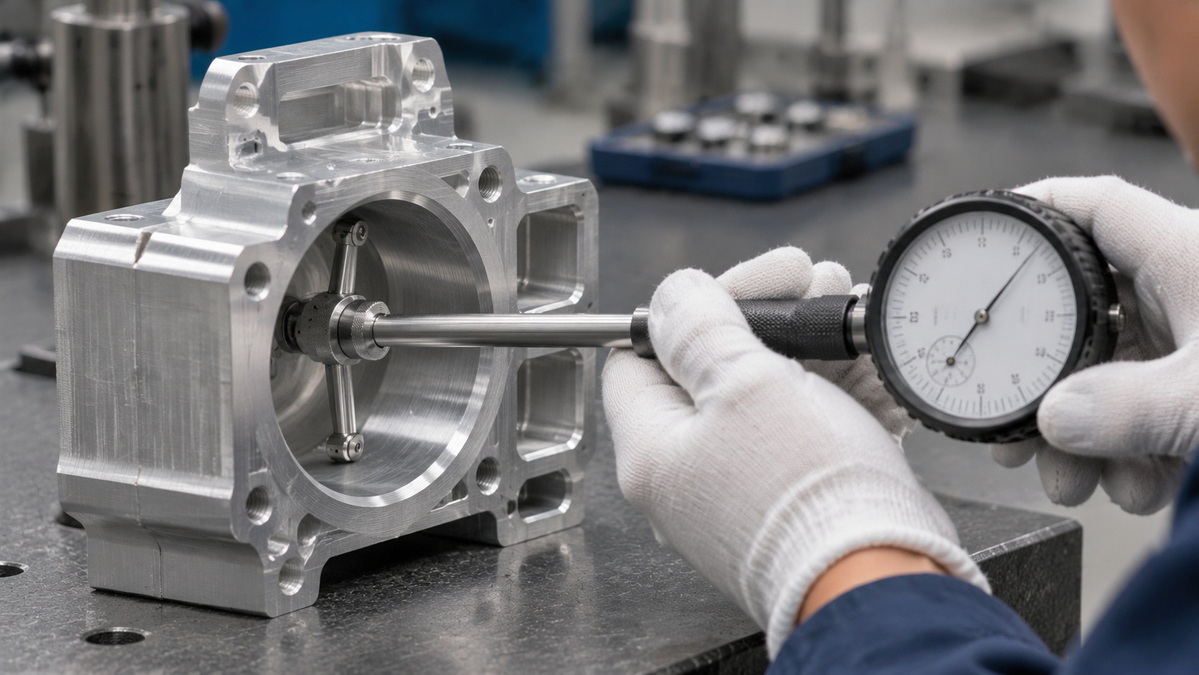
CNC machining removes material from a blank using computer-controlled tools. It is a strong starting point for accessible features where size, location, or finish controls performance. Think bearing seats, locating holes, threaded interfaces, and flat faces that clamp against a gasket.
Consider a locating bore specified at 20.00 ± 0.02 mm. The acceptable diameter is 19.98 to 20.02 mm. That number alone does not tell a machinist where the bore must sit relative to the mounting face. Nor does it tell an inspector how to measure it. Provide a drawing that identifies the functional reference surfaces, or datums, and specify any other requirements that affect the fit.
For a leak test, define the condition of the whole interface: groove geometry, sealing-face finish, mating hardware, fastener torque, and the leak limit. A prototype that passes with a better sealing surface than production can deliver may give false confidence.
Machining is a useful route when the final part will also be cut from a specified engineering plastic or metal stock. If a fixture bracket will be made from 6061-T6 aluminum, testing a bracket machined from the specified stock is generally more informative for load and deflection than testing a resin stand-in.
Match more than the material name. Specify the relevant stock form, temper or heat treatment, and any coating or surface treatment that affects the test. Use the intended fasteners and mounting arrangement. For a wear test, include the real mating surface where practical: changing the counterface can change the result even when the prototype material is correct.
For parts destined for a different production process, limit the conclusion. A machined plastic prototype can validate an assembly interface, but it cannot reproduce molding effects such as weld lines, where two flows of molten plastic meet. If the likely failure is a crack near a weld line, test a molded sample.
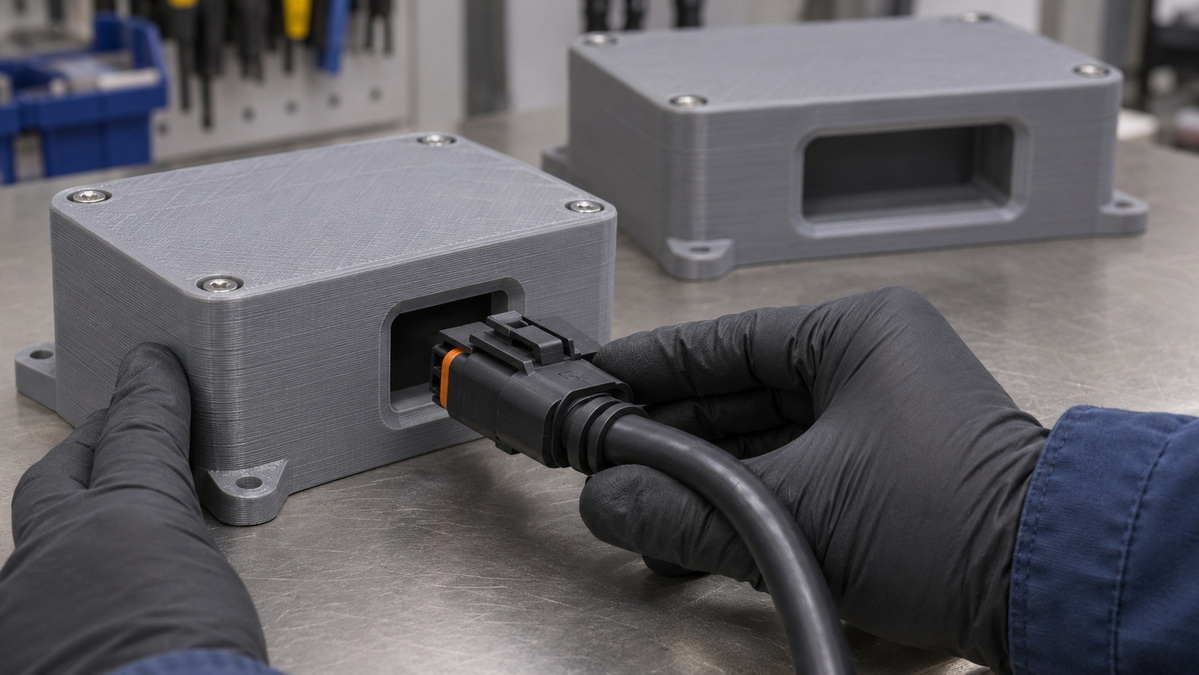
3D printing builds a part layer by layer. It is especially useful when the design is still changing and the team needs physical feedback before investing in precise features. Print alternative housing layouts, for example, and use the real connector and cable to check insertion angle, routing, and removal access.
Set the test boundaries before reviewing the sample. A printed enclosure might pass an assembly trial even if its strength is unrepresentative. Conversely, a latch that breaks on a visual-model resin prototype may say more about the resin than the geometry. Record the observation without drawing conclusions the sample cannot support.
Additive manufacturing can make curved passages and enclosed geometries that conventional cutting tools cannot reach directly. A printed manifold can help you compare layouts or check for interference. If the goal is to make a quantitative claim about pressure drop, however, verify the passage dimensions and internal surface condition. A difference in either could influence the measurement.
Choose the print process as carefully as the material:
- Fused deposition modeling (FDM) extrudes thermoplastic and is useful for inexpensive layout checks and simple fixtures. Record the build orientation before interpreting a load test.
- Stereolithography (SLA) cures liquid resin and works well for detailed geometry and visual fit checks. Do not equate an "ABS-like" designation with the properties of molded ABS.
- Selective laser sintering (SLS) fuses polymer powder. Nylon SLS parts can support assembly trials and some movement or snap-fit checks, but their results should not substitute for durability data from the intended production part.
- Metal laser powder bed fusion builds metal parts from powder. If the production part will also be printed, use a representative build orientation, heat treatment, and finishing route for performance testing.
Build direction is not a minor detail. In one published study of laser powder bed fusion 316L stainless steel, the average elastic modulus, a measure of stiffness, was 158.7 GPa for vertical specimens versus 196 and 199 GPa for two horizontal sets. These are study-specific results, not design values. The practical lesson is to record orientation and processing conditions when comparing results.
1. Define a pass or fail result. Replace "check strength" with an observable requirement, such as "support a 250 N load for 60 seconds with no more than 0.5 mm of permanent deflection." These figures are illustrative; use limits derived from your product requirements.
2. Identify what could invalidate the result. A fit test may depend on hole location. A heat test may depend on the material and wall thickness. A repeated assembly test may depend on thread strength, friction, and wear.
3. Specify the features that matter. Send a 3D model for geometry and a drawing for critical dimensions, datums, finishes, and inspection requirements. Leave noncritical features at standard tolerances where possible.
4. Inspect the sample before testing. Record critical dimensions and the material, finish, or print settings needed to interpret the result. Otherwise, you may spend a test cycle investigating an out-of-spec prototype rather than evaluating the design.
5. State exactly what passed. Write "connector access verified with printed enclosure" or "bearing fit verified on inspected machined sample." List the open questions and reserve production approval for samples that represent the final process where it matters.
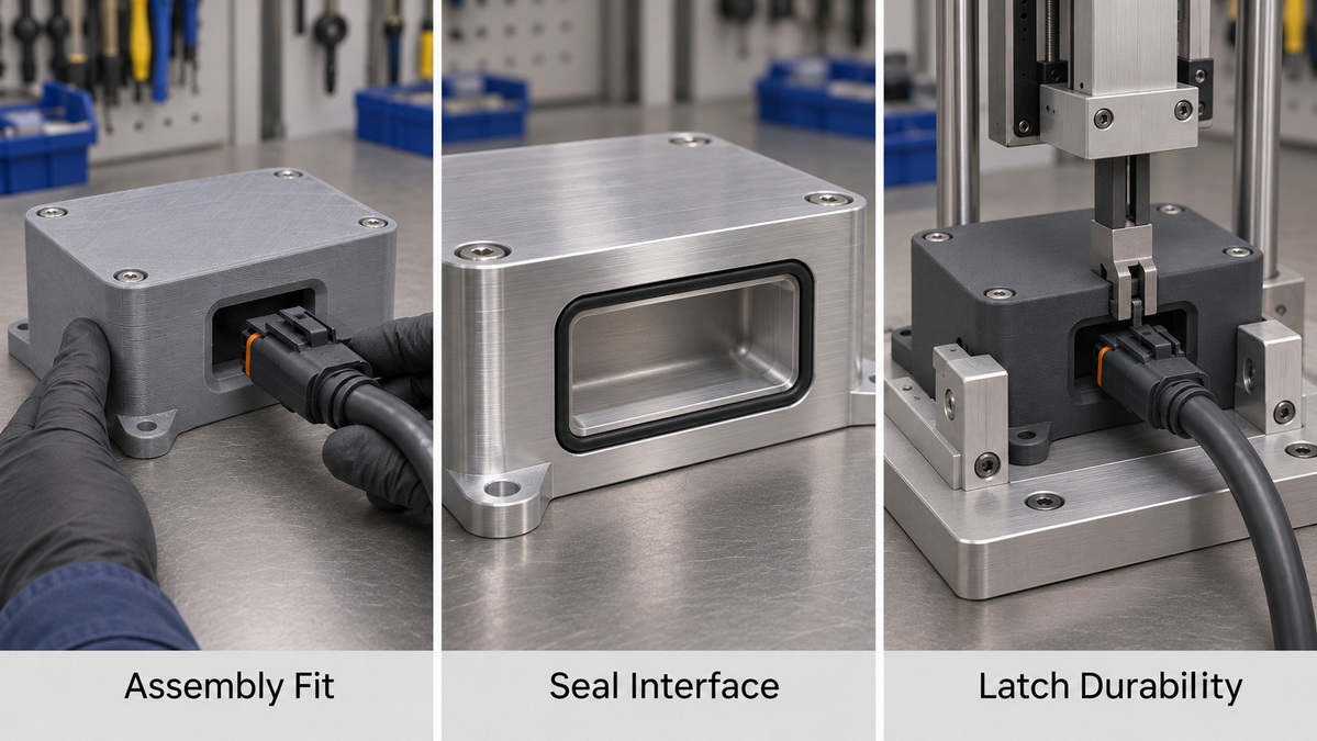
Imagine an electronics housing with a gasket, a snap latch, and a recessed connector. The production plan is injection molding. The team needs to know whether technicians can reach the connector, whether the gasket design seals, and whether the latch survives repeated service.
Start with several printed layouts. Use the actual connector, cable, and service tool. If the cable cannot bend into position or the tool hits the housing wall, revise the geometry before paying for a precision prototype.
Next, machine the seal interface if the team needs to isolate groove geometry and gasket compression. Measure the groove and test the assembly with the intended gasket and fasteners. A pass supports the interface design under those test conditions. It does not show the molded housing will have the same flatness.
Finally, test molded samples for the questions that depend on molding: latch durability, housing warpage, and sealing after assembly. This staged plan keeps a quick print from carrying too much evidentiary weight and avoids asking an expensive machined sample to answer questions it cannot resolve.
The same principle applies to sheet metal. A machined block may verify a bracket's mounting points. If the test depends on bend geometry or the springback that occurs after forming, use a laser-cut and bent sample, then move to stamped samples when the production stamping process itself needs validation.
A low unit price is not the same as a low test cost. A quick print can be excellent value when three layouts need reviewing. It can become expensive if the team runs a full test and later discovers the sample could not represent the failure mode. Machining may cost more upfront but make sense if one accurate interface is the only unresolved risk.
Compare quotes on the same scope. Include material availability, finishing, inspection, and shipping, not just fabrication time. Ask whether the quoted part is ready for the test or still needs tapping, inserts, surface finishing, or measurement. For a hybrid part, confirm which features will be finished after printing and how they will be located during machining.
Send U-Need your CAD file, drawing, intended production process, and test conditions. Mark the critical features and state what counts as a pass. For international brands, distributors, and manufacturers, U-Need can review where precision machining, a fabricated sheet metal sample, or prototype tooling fits into the validation plan. Tell us what the prototype must prove so the quote reflects the material, finish, and inspection your decision depends on.
Yes. It can be useful for assembly, clearances, movement, and selected load or flow tests. The result is meaningful when the material, build orientation, dimensions, and finish are representative of the behavior being measured.
Generally, CNC machining is the better starting point for tight tolerances on accessible features. Neither process has a universal accuracy figure. Ask for capability on the specific feature, in the chosen material, and verify the sample before using it to judge a fit.
Use a suitable print to check engagement, alignment, and release access. If the requirement is repeated use or retention over time, validate it on samples that represent the final material and process, especially for injection-molded latches.
Yes. Where the geometry allows, print the complex shape and machine selected bores, threads, or sealing surfaces. Plan for machining allowance, tool access, and a reliable way to hold and locate the part.
It can answer some questions about fit, mounting, and interface geometry. It cannot validate molding-specific effects such as shrinkage, warpage, or weld-line performance. Use representative molded parts when those effects matter to the decision.
1.Protolabs, [3D Printing vs. CNC Machining: Know the Differences]. Process selection, geometry constraints, stock materials, and finishing considerations. [protolabs]
2.Protolabs Network, [3D Printing vs. CNC Machining: Which Is Better for Prototyping and End-Use Applications?]. Comparison of additive processes, material options, dimensional accuracy, and lead-time considerations. [hubs]
3.Protolabs, [3D Printing vs. CNC Machining vs. Injection Moulding]. Manufacturing routes for design iteration, precision interfaces, and the transition to molding. [protolabs]
4.National Institute of Standards and Technology, [Challenges in Tolerance Transfer for Additive Manufacturing]. Build direction, process variation, and datum references in additive manufacturing. [nist]
5.*Materials*, [Anisotropy of Mechanical Properties and Residual Stress in Additively Manufactured 316L Stainless Steel]. Experimental source for the elastic modulus comparison across three build orientations. [pmc.ncbi.nlm.nih]


