Views: 220 Author: U-Need Publish Time: 2026-11-24 Origin: Site
Content Menu
● What Makes a Prototype Production-Like?
● When Rapid CNC Prototyping Gives You the Closest Match
>> Match the Material Grade, Stock Form, and Condition
>> Check Critical Fits in the Finished Condition
>> Know What a Machined Sample Cannot Validate
● When 3D Printing Produces the More Useful Prototype
>> Choose the Printing Process for the Test
>> Match the Additive Production Route When Printing Is the End Goal
● CNC Machining vs 3D Printing: Compare the Cost of a Test-Ready Part
● Two Prototype Plans That Avoid False Confidence
>> Example 1: An Aluminum Housing With a Gasket Seal
>> Example 2: An Injection-Molded Cover With Snap-Fits
● How to Specify a Production-Like Prototype in an RFQ
● Discuss Your Prototype-to-Production Plan With U-Need
>> Is CNC machining more accurate than 3D printing?
>> Is 3D printing always faster for rapid prototyping?
>> Can a CNC prototype become the first production part?
>> Are 3D-printed prototypes strong enough for functional testing?
>> What is the best prototype for a stamped or bent sheet-metal part?
Rapid CNC prototyping usually produces more production-like parts when the final component will also be machined from the same material and stock condition. It is the better starting point for checking precision fits, threads, sealing surfaces, and finished dimensions. 3D printing is often the better choice for early design iterations, complex internal geometry, or parts that will ultimately be printed. If production will use injection molding, stamping, or cold forging, neither method alone can validate the finished part.
The most useful question in a prototype review is not "Which process makes the best part?" It is "Which production decision does this sample need to support?" A printed housing can reveal a connector clearance problem just as effectively as a machined one. But if the decision is whether the housing will seal after repeated assembly, the material, surface finish, and manufacturing route matter much more.
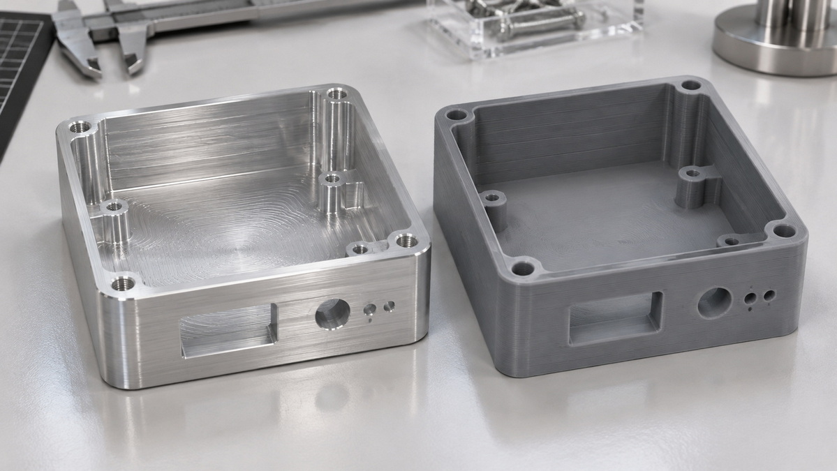
A production-like prototype reproduces the characteristics that matter to a specific test or approval. That may mean matching the geometry of an assembly, using the specified material, or reproducing how the part behaves after manufacturing and finishing. One sample does not have to do all three, but its approval scope should make clear what it proves.
| What you need to verify | Best starting point | What the result does not prove |
|---|---|---|
| Envelope, layout, and assembly access | 3D-printed model | Production strength, finish, or dimensional repeatability |
| Bearing fit, threaded engagement, or seal geometry on a machined component | CNC prototype with specified material, finish, and inspection | Repeatability across a full production run |
| Internal passages that cutting tools cannot reach | Industrial 3D printing, with machining on critical interfaces if needed | Leak tightness or internal quality without dedicated testing |
| Molded snap life, warpage, or visible molding marks | Molded samples in the intended resin | Final-tool capability if the trial tool differs significantly |
| Springback or fit after bending or stamping | Formed sheet-metal samples | Process capability without representative tooling and multiple samples |
A useful distinction for buyers: prototype approval and production approval are separate decisions. One conforming sample shows that a supplier made one acceptable part. It does not establish the variation you should expect across a batch.
CNC machining removes material from bar, plate, or another solid blank. For a final part specified in 6061-T6 aluminum, a CNC prototype made from the same grade, temper, and stock form provides a more relevant basis for functional testing than a look-alike resin print. The same logic applies to an acetal guide or a stainless steel mounting plate when the prototype and production material specifications align.
Do not treat an alloy or polymer name as the full specification. A bracket machined from plate does not automatically behave like a casting or forging with a similar alloy designation. Likewise, a housing machined from plastic stock cannot show what happens when molten resin flows around a molded boss. Match material and process to the property you need to verify.
CNC machining is particularly useful when a few features control assembly: a locating bore, a flat mounting face, a seal groove, or a pattern of threaded holes. These are the dimensions to identify on the drawing rather than asking for the tightest available tolerance across the entire part.
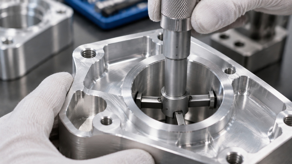
For example, a drawing might call for a 20.00 mm bore with a ±0.02 mm tolerance, giving an acceptance range of 19.98 to 20.02 mm. That range is an illustrative requirement, not a general CNC capability. The supplier still needs to confirm feasibility for the material, geometry, setup, and finish. If the bore will be anodized, specify whether it should be measured before or after finishing and whether masking is required. Otherwise, a bore that passes inspection at the machine may not meet the drawing in its delivered condition.
A CNC-machined plastic housing can help verify screw access, board clearance, and the position of a gasket. It cannot tell you where a molded part will develop a weld line, where flow fronts meet, or whether a thick rib will leave a visible sink mark. Similarly, a bracket machined from a solid block may locate mounting holes accurately but says little about how a sheet-metal bracket will spring back after bending. Use the machined sample to settle the questions it can answer, then move to a representative process for the rest.
3D printing describes several manufacturing processes, not a single level of accuracy or durability. The right choice depends on what the sample needs to do:
- Fused deposition modeling (FDM) extrudes thermoplastic. It is useful for quick layout checks, but build orientation can affect strength when a part is loaded across layers.
- Stereolithography (SLA) cures liquid photopolymer and can reproduce fine details for appearance or fit reviews. A smooth resin sample is not proof that the final molded plastic will handle the same loads, temperatures, or repeated deflection.
- Selective laser sintering (SLS) fuses polymer powder. It is useful for complex nylon prototypes and functional trials, provided the team checks whether the printed material and finish suit the test.
- Metal powder bed fusion can form internal passages and shapes that are difficult to machine directly. Bearing seats, threads, or sealing faces can then be machined where the design requires tighter control.
For a part that will be 3D-printed in production, a prototype made with the intended print process is generally more representative than a machined stand-in. Record the material, build orientation, and post-processing steps so the sample is useful for comparison. Machining a prototype from wrought metal can validate its external geometry, but not the material behavior of the printed version.
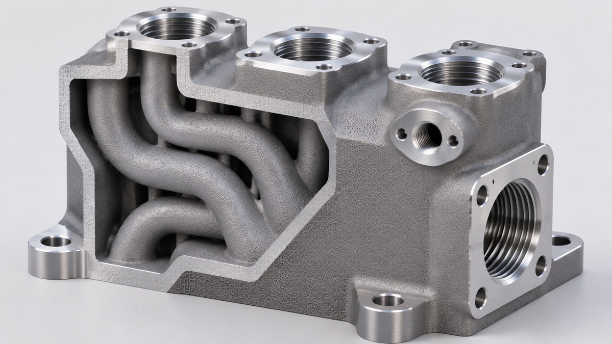
A hybrid route can make sense when the same part needs two different kinds of accuracy. For example, print a manifold to reproduce its internal channels, then machine the port faces and threads. The print validates the geometry that would be difficult to cut; machining provides controlled sealing interfaces. The finished assembly still needs a leak or pressure test against its actual acceptance criteria.
A low-cost or fast print is attractive when you only need to learn whether components fit together. The calculation changes when the print needs inserts, surface finishing, or secondary machining before the test can begin. Conversely, a CNC prototype that requires several setups may be poor value if the design is likely to change after one layout review.
Ask suppliers to quote the same deliverable: the required quantity, material, finish, secondary operations, inspection report, and handover date. Compare time to a part ready for testing, not time to the first unfinished sample. For international orders, separate manufacturing lead time from transit so you can tell whether a faster process will actually move up the review.
Suppose the final product is a CNC-machined enclosure with a sealing face, a gasket groove, threaded fasteners, and an internal circuit board. Print the first version if the open questions are whether the board clears the cover and whether an installer can reach the connectors. Those checks do not need a finished aluminum enclosure.
Once the layout is stable, machine the next sample from the specified stock. Inspect the sealing face and groove after the relevant finishing operations. Assemble it with the intended gasket and fasteners, then use the planned leak test. The printed sample helps prevent an expensive layout error; the machined sample tests a different question: whether the finished interfaces work together.
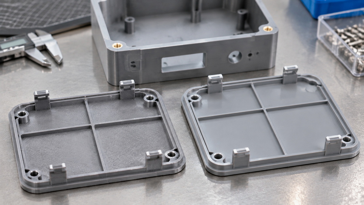
Start with a printed cover to check installation sequence, finger access, and clearance around the mating assembly. A printed snap can help the designer see where it engages, but it should not be used on its own to approve retention force or fatigue life.
Before production release, test molded samples in the intended resin. Check insertion force, retention after repeated removal, visible surfaces, and overall warpage. If the samples came from a trial tool, identify differences in gating, cooling, or cavity layout before using those results to approve parts from the final mold.
A useful request for quotation tells the supplier what decision the sample must support. Send the current 3D model and a revision-controlled drawing, then add:
1. The intended production process and the exact material grade, including temper, stock form, or resin grade where relevant.
2. The critical dimensions and their reference surfaces. Identify which features control assembly, sealing, alignment, or motion.
3. The required finish, any areas to mask, and the stage at which critical features must be inspected.
4. The prototype quantity, test purpose, and inspection records needed to accept the samples.
5. Any approved substitutions and their limits. For example: "Printed polymer is acceptable for clearance checks only; do not use it for load testing."
If the production route is still open, request separate quotes for a design-review sample and a functional prototype. That lets you compare two useful deliverables instead of forcing one sample to answer every question.
Send U-Need your 3D model, drawing, target production process, and the test your prototype must pass. For custom precision parts, injection molds, stamping or cold-forging dies, and sheet-metal fabrication, use that review to decide which features to validate now and which require production-process samples before release.
Generally, CNC is the better starting point for close-tolerance bores, flat faces, and controlled feature locations. Industrial printing accuracy varies by process, material, geometry, build orientation, and post-processing. Ask for a feature-specific tolerance and inspection method rather than comparing general accuracy figures.
No. Printing can shorten early iterations because it does not require cutting-tool access or conventional machining setups. But post-curing, support removal, secondary machining, and inspection can narrow the gap. Compare the dates when both options will be ready for the same test.
Yes, if it meets the released drawing, uses approved material and processes, and passes the required inspection. One acceptable part, however, does not show that the process will consistently meet requirements as output increases.
They can be, if the print process, material, and build orientation suit the load and environment. A sample can be strong enough for an assembly trial without being representative enough for fatigue, pressure, or temperature qualification.
Use a printed model for early clearance checks. Use a sample formed from the intended sheet grade and thickness when bend radii, springback, or fit after forming matter. If the test depends on the final die or forming sequence, use parts produced with representative tooling.
1.[Protolabs — "3D Printing vs. CNC Machining: Know the Differences"]. Background on subtractive and additive process selection, material options, tool access, and geometry constraints. [protolabs]
2.[Protolabs Network — "3D Printing vs. CNC Machining: Which Is Better for Prototyping and End-Use Parts?"]. Technical comparison of feature accuracy, finishing, turnaround, and secondary machining. Supplier figures are process-specific, not universal tolerances. [hubs]
3.[Formlabs — "Validating Isotropy in SLA 3D Printing"]. Background on directional mechanical properties and how build orientation can affect FDM parts. [formlabs]
4.[Formlabs — "SLS 3D Printing vs. Injection Molding: When to Replace Molded Parts With 3D-Printed Parts"]. Comparison of polymer powder-bed printing and injection molding, including geometry and process repeatability. [formlabs]
5.[FACTUREE — "3D Printing vs. Injection Molding for Prototypes: When Is Each Method the Better Choice?"]. Background on molding shrinkage, tool design, process control, and when to move from a printed model to molded samples. [facturee]
6.[NIST — "Findings from the NIST/ASTM Workshop on Mechanical Behavior of Additive Manufacturing Components"]. Technical context on the relationships among additive manufacturing processes, material structure, mechanical properties, and qualification. [nist]


