Views: 233 Author: U-Need Publish Time: 2026-09-22 Origin: Site
Content Menu
● What Is Close Tolerance Machining?
>> Typical Tolerance Levels in Machining
>> Why General Tolerances Are Important
● Close Tolerance Machining vs General Machining
● Which Parts Actually Need Close Tolerance Machining?
>> Bearing Seats and Bearing Bores
>> Mating Shafts, Bushings, and Sliding Components
>> Sealing Surfaces and Fluid-Control Parts
>> Parts With Moving Interfaces
>> Injection Mold Components and Tooling Interfaces
>> Medical, Aerospace, and Safety-Critical Components
● Which Parts Usually Do Not Need Close Tolerance Machining?
● The Hidden Cost of Over-Tolerancing
● How to Select the Right Tolerance
>> Define the Feature Function
>> Establish Functional Datums
>> Match the Requirement to the Process
>> Define the Inspection Method
● Practical Example: Motor Housing Design
● Manufacturing Considerations for Different Part Types
>> Custom Precision Machined Parts
>> Injection Mold Manufacturing
>> Stamping Dies and Cold-Forging Dies
● Summary
● FAQ
>> What is considered a close machining tolerance?
>> Is close tolerance machining always more expensive?
>> Which machined features most often need tight tolerances?
>> Can a precision-machined part use general tolerances?
>> How can I avoid over-tolerancing a part?
>> Is GD&T useful for close tolerance machining?
>> Can sheet metal parts have close tolerances?
>> What information should be included in a machining request?
Choosing between close tolerance machining and general machining is not simply a question of whether higher accuracy is better. It is a decision that affects part function, assembly reliability, production speed, inspection effort, material utilization, and total manufacturing cost.
For global brands, distributors, and manufacturers, the most effective strategy is to apply tighter tolerances only where they create real functional value. A bearing seat may need highly controlled dimensions. A non-mating exterior edge on a support bracket often does not.
At U-Need, we support customers with custom precision parts machining, mold manufacturing, and sheet metal fabrication. From early drawing review to final inspection, our focus is to understand what each feature must do in the finished product. This helps customers avoid unnecessary machining cost while protecting the performance of critical parts.
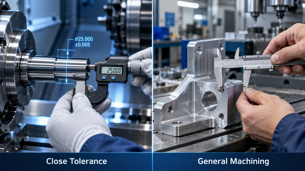
Close tolerance machining is the manufacturing of a component within a narrowly controlled dimensional range. A tolerance defines how much a feature can vary from its specified nominal size while remaining acceptable.
For example, a shaft diameter specified as 10.00 mm ±0.01 mm must remain between 9.99 mm and 10.01 mm. If the shaft falls outside this range, it may not fit correctly into its mating bore, bearing, bushing, seal, or assembled mechanism.
Close tolerance requirements can apply to more than basic length, width, thickness, and diameter. They can also control the geometric condition and relationship of features, including:
- Flatness
- Straightness
- Circularity
- Cylindricity
- Concentricity
- Perpendicularity
- Parallelism
- Feature position
- Runout
- Surface roughness
Producing tight-tolerance parts usually requires more than a capable CNC machine. It often involves careful process planning, stable fixturing, controlled cutting conditions, suitable materials, calibrated measuring equipment, in-process inspection, and qualified final inspection.
There is no single tolerance value that automatically defines a part as precision machined. The achievable tolerance depends on part size, material, geometry, wall thickness, machining method, tooling, machine capability, measurement access, and environmental conditions.
The following ranges provide a practical starting point for engineering discussions.
| Tolerance Category | Typical Dimensional Expectation | Common Applications |
|---|---|---|
| General machining | Approximately ±0.1 mm to ±0.5 mm | Covers, frames, brackets, support parts |
| Standard CNC machining | Approximately ±0.05 mm to ±0.1 mm | Housings, general mechanical components, mounting plates |
| Close tolerance machining | Approximately ±0.01 mm to ±0.05 mm | Bearing seats, shafts, guide features, sealing interfaces |
| Ultra-precision machining | Below ±0.01 mm for selected features | Optical, medical, aerospace, and specialized high-performance parts |
These ranges should not be treated as universal production promises. A short, rigid aluminum bore may be controlled differently from a long stainless-steel shaft, a thin-wall housing, a deep cavity, or a heat-treated tool steel component.
General machining means manufacturing a part to normal, practical tolerances that are appropriate for its function. It does not mean low-quality machining. Instead, it means the manufacturer controls each dimension to a level that makes sense for the product's intended use.
Many parts include features that do not require extremely high precision. For example, a sheet metal equipment bracket may need accurately positioned mounting holes so it aligns with another assembly. However, the outer profile, clearance edges, decorative cutouts, or non-contact surfaces may not need narrow tolerances.
General tolerances are commonly used for dimensions that are not individually specified on a drawing. These tolerances provide a practical default range for linear dimensions, angles, chamfers, and selected geometrical requirements.
General tolerances help design teams communicate clearly without overloading a drawing with unnecessary requirements. They also help manufacturers understand which dimensions are functional and which dimensions allow reasonable production variation.
For example, a general tolerance system may include different classes based on the level of accuracy required.
| General Tolerance Class | Typical Use | Relative Manufacturing Cost |
|---|---|---|
| Fine | Controlled parts with moderate functional requirements | Higher |
| Medium | Standard machined and fabricated components | Balanced |
| Coarse | Structural components, brackets, non-critical profiles | Lower |
| Very coarse | Large fabricated parts or non-critical dimensions | Lowest |
The correct tolerance class depends on the part's function, material, process, production volume, assembly method, and customer expectations.
A general tolerance approach is especially useful when a part has only a few critical dimensions. Instead of applying a narrow tolerance to every surface, designers can control the important functional features individually and allow wider variation on the rest of the part.
The difference between close tolerance machining and general machining is not simply the type of CNC machine used. The real difference is the amount of planning, control, inspection, and manufacturing effort required to produce consistent results.
| Factor | Close Tolerance Machining | General Machining |
|---|---|---|
| Main purpose | Protect critical part function and assembly performance | Produce functional parts efficiently |
| Feature importance | Critical-to-function, critical-to-quality, or safety-related | Non-critical, clearance-based, or structural |
| Dimensional range | Narrow and feature-specific | Wider and often based on general tolerance requirements |
| Workholding | High-stability fixtures and controlled datum locations | Standard fixturing methods |
| Machining process | More careful tool selection, compensation, and process control | Conventional machining parameters |
| Inspection level | Frequent measurement, gauges, CMM checks, inspection records | Standard first-article and final inspection |
| Cycle time | Often longer | Usually shorter |
| Scrap sensitivity | Higher because the acceptable range is narrower | Lower because variation is more acceptable |
| Production cost | Higher due to machining and quality-control demands | More economical for non-critical features |
| Typical parts | Bearing seats, shafts, valve bodies, mold inserts, guide components | Covers, brackets, frames, housings, support plates |
The best practice is simple: apply precision where the part must perform a critical job. Do not specify close tolerances merely because they are technically achievable.
A part should receive close tolerance machining when even a small amount of variation could affect its functional performance, assembly condition, safety, reliability, or service life.
The most useful question is not, "Can this part be made to a tight tolerance?" The better question is, "What happens if this dimension changes?"
If a small dimensional change can cause a product to fail, bind, leak, vibrate, wear prematurely, or become difficult to assemble, the feature may need close control.
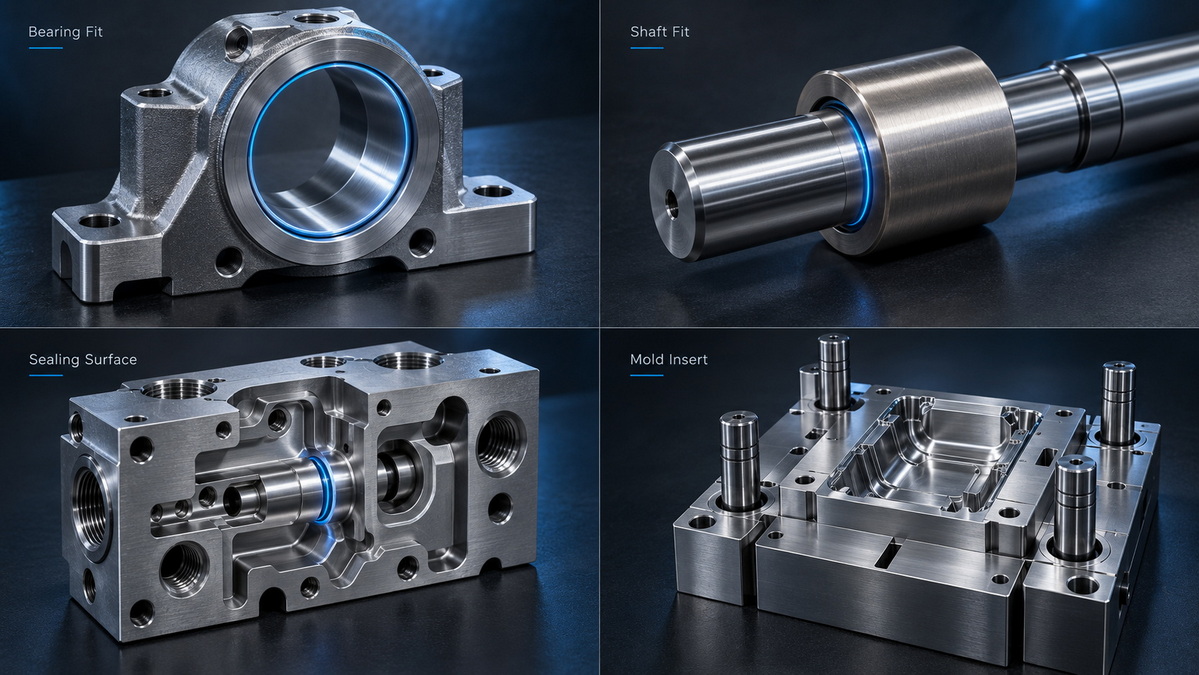
Bearing interfaces are among the most common applications for close tolerance machining. The fit between a bearing and its housing or shaft directly affects rotation, load distribution, noise, vibration, heat generation, and service life.
If a bearing bore is too large, the bearing outer ring may move inside the housing. This can create vibration, fretting corrosion, noise, and reduced positional stability. If the bore is too small, assembly can become difficult and the bearing may experience distortion or unintended preload.
Critical bearing-related features often include:
- Bearing bore diameter
- Shaft journal diameter
- Roundness
- Cylindricity
- Concentricity
- Shoulder position
- Face perpendicularity
- Surface roughness
- Runout
Common applications include motor housings, gearboxes, pumps, spindles, robotic joints, precision reducers, conveyors, and high-speed rotating equipment.
Close tolerance machining is essential when components must slide, rotate, locate, press-fit, or operate with controlled clearance.
Typical examples include:
- Guide pins and guide bushings
- Hydraulic valve spools and bores
- Pneumatic cylinder components
- Precision plungers
- Linear guide elements
- Gear shafts
- Locating pins
- Precision sleeves
- Press-fit components
- Mechanical locking features
These features often require a carefully designed fit. Depending on the application, the relationship may be a clearance fit, transition fit, or interference fit.
A good fit design must consider more than the nominal dimensions. Engineers should also evaluate lubrication, operating temperature, surface finish, coating thickness, material hardness, contamination, assembly force, and thermal expansion.
Parts used in hydraulic, pneumatic, vacuum, automotive fluid, medical-fluid, and industrial process-control systems often need close machining control.
A small dimensional change can affect sealing pressure, fluid flow, leakage rate, and long-term reliability.
Common close-tolerance features include:
- Valve bores
- Hydraulic manifolds
- Pump housings
- Seal grooves
- O-ring gland features
- Precision nozzles
- Threaded fluid connections
- Sealing faces
- Piston bores
- High-pressure fitting interfaces
For example, the dimensions of an O-ring groove influence compression, sealing force, and resistance to extrusion. A groove that is too shallow, too deep, too wide, or too narrow can reduce sealing performance even if the rest of the part is correctly manufactured.
Any product containing controlled movement should receive careful tolerance review. This includes assemblies with pivots, sliders, gears, hinges, rotating shafts, linkages, actuators, or intentional interference fits.
Common examples include:
- Industrial automation mechanisms
- Robotic end effectors
- Packaging machinery
- Aerospace mechanisms
- Medical instruments
- Automotive actuators
- Mold slides and lifters
- High-cycle industrial equipment
- Precision fixtures
- Camera and optical positioning systems
For moving assemblies, a single dimension rarely tells the complete story. Multiple parts interact with one another, and small variations can accumulate across the assembly.
This is why tolerance stack-up analysis is important. It evaluates the combined effect of individual part variations to determine whether the final assembly will still operate correctly in the worst-case condition.
Mold manufacturing often requires a combination of close tolerance machining and general machining.
Critical mold features may include:
- Core inserts
- Cavity inserts
- Parting surfaces
- Shut-off surfaces
- Guide pillars
- Guide bushings
- Slider interfaces
- Wear plates
- Ejector-pin holes
- Gate inserts
- Mold locating rings
- Cooling-channel connections
The core, cavity, and shut-off surfaces can directly influence the dimensions, appearance, flash control, and consistency of the molded plastic part. Guide and alignment components also need accurate machining to support stable mold movement over repeated production cycles.
However, not every area of a mold base requires the same high level of control. Non-critical outer surfaces, general pockets, mounting areas, and clearance regions can often be machined to more practical tolerances.
Medical, aerospace, automotive safety, and high-performance industrial applications may require strict dimensional control because failure consequences are higher.
Close tolerance machining can be important for:
- Surgical instruments
- Implant-related components
- Catheter shafts and fittings
- Medical device housings
- Aerospace actuator components
- Flight-control mechanisms
- Sensor housings
- High-pressure connectors
- Safety-locking mechanisms
- Precision optical mounts
- High-speed rotor components
In these industries, dimensional accuracy is often only one part of the quality requirement. Customers may also need material traceability, controlled processes, surface-finish verification, inspection documentation, and repeatable batch-to-batch manufacturing.
General machining is often the better option when normal dimensional variation does not affect the part's performance, assembly, safety, or appearance.
Typical examples include:
- Equipment covers and guards
- Mounting brackets with adequate fastener clearance
- Structural plates
- Support blocks
- General housings
- Welded fabrication components
- Sheet metal enclosures
- Non-mating exterior surfaces
- Decorative cutouts
- Shipping fixtures
- Simple protective frames
- Rough-machined mold base features
A laser-cut and bent equipment bracket provides a useful example. The mounting-hole locations may need moderate control because they align the bracket with another component. However, the external edge profile may not need extremely tight tolerances. Applying unnecessary precision to every edge would increase programming time, setup requirements, inspection work, and production cost without improving the bracket's actual function.
Over-tolerancing happens when a drawing applies tighter requirements than the part actually needs. It is one of the most common causes of avoidable cost in CNC machining, mold manufacturing, and metal fabrication.
A tolerance that is unnecessarily narrow can force the manufacturer to use more complex processes, additional measurement steps, and slower production methods.
Potential cost increases include:
- More expensive machine time
- Additional machining setups
- Specialized fixtures
- Slower cutting speeds
- More frequent tool compensation
- Higher tooling requirements
- In-process measurement
- Detailed final inspection
- Coordinate measuring machine checks
- Higher rejection risk
- More scrap and rework
- Longer lead times
- Lower production yield
The cost impact can become significant in larger production volumes. A requirement that adds only a few seconds to a machining cycle may create substantial cost when multiplied across thousands of parts.
At the same time, under-tolerancing can create even more serious problems. Loose critical features may cause assembly delays, poor quality, leakage, vibration, customer complaints, warranty claims, or field failures.
The objective is not to choose the tightest possible tolerance. The objective is to choose the right tolerance for the part's real function.
A well-designed tolerance strategy begins before production. It should be developed during part design, drawing preparation, and manufacturability review.
Start by asking what the feature does in the finished product.
- Does it locate another part?
- Does it control a bearing or bushing fit?
- Does it create a seal?
- Does it affect moving performance?
- Does it support a load?
- Does it influence vibration?
- Does it affect electrical contact?
- Does it control heat transfer?
- Does it establish a visible gap or flush condition?
- Does it affect user safety?
If the feature does not have a direct functional role, a general tolerance may be sufficient.
A close tolerance dimension must be measured from a stable and meaningful reference. These references are called datums.
For example, a mounting-hole pattern should be controlled relative to the surfaces and features that actually locate the part in the final assembly. If the datum system does not reflect the functional assembly condition, the part may meet the drawing but still fail during installation.
Functional datums are especially important for:
- Hole patterns
- Bearing bores
- Mating faces
- Shaft locations
- Mold inserts
- Sheet metal bends
- Precision tool components
- Multi-axis machined housings
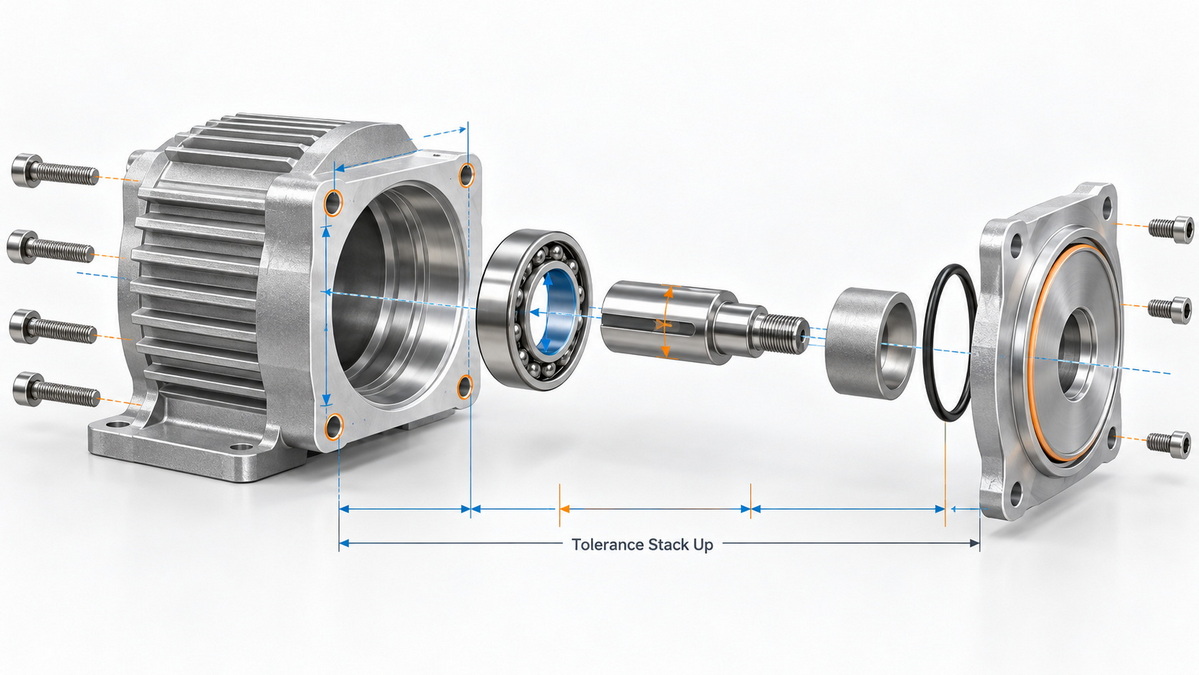
Tolerance stack-up analysis evaluates how variation accumulates across multiple dimensions and components.
Consider a simple assembly with a housing, bearing, shaft, spacer, cover, and fasteners. Each part may be individually within tolerance, but the total variation could still create poor alignment, excessive end play, interference, or preload.
A proper stack-up review should consider:
- Component dimensions
- Hole positions
- Material thickness
- Bend variation
- Coating thickness
- Thermal expansion
- Assembly sequence
- Fastener clearance
- Fixture repeatability
- Wear during use
- Load-related deflection
This analysis is particularly valuable for moving assemblies, press fits, sealing systems, and products exposed to changing temperatures.
The manufacturing method must be capable of producing the required tolerance consistently.
| Manufacturing Process | Features That Often Need Special Tolerance Review |
|---|---|
| CNC milling | Pockets, bores, profiles, hole positions, flatness |
| CNC turning | Diameters, runout, concentricity, shoulders, threads |
| Grinding | Precision diameters, flatness, surface finish, bearing fits |
| Sheet metal fabrication | Hole positions, bend angles, formed features, flatness |
| Injection mold manufacturing | Cavities, cores, parting lines, slides, guide components |
| Stamping die manufacturing | Punch alignment, die clearance, guide features |
| Cold-forging die manufacturing | Die cavity dimensions, alignment features, wear surfaces |
Material properties also matter. Aluminum, stainless steel, carbon steel, brass, titanium, engineering plastics, and hardened tool steel respond differently to machining forces and temperature changes.
Part geometry also affects manufacturability. Deep bores, thin walls, long slender shafts, small internal radii, complex contours, and difficult-to-access inspection features may require special process planning.
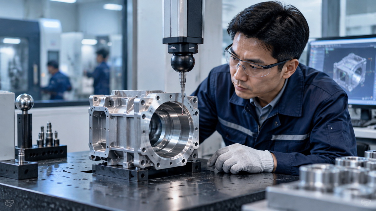
A tolerance should be linked to a reliable measurement method.
Typical inspection tools include:
- Calipers for non-critical external dimensions
- Micrometers for precision diameters
- Pin gauges for holes
- Thread gauges for threaded features
- Bore gauges for internal diameters
- Height gauges for step and datum measurements
- Surface plates for flatness checks
- Coordinate measuring machines for complex geometry
- Optical systems for small or delicate parts
- Surface roughness testers for finish requirements
For critical dimensions, the inspection plan should identify the measurement tool, measurement frequency, sampling quantity, acceptance criteria, and documentation requirement.
Consider a machined aluminum motor housing that includes a bearing bore, mounting holes, cable-entry features, cooling fins, and external walls.
Not every feature should receive the same tolerance requirement.
| Motor Housing Feature | Recommended Tolerance Approach | Reason |
|---|---|---|
| Bearing bore | Close tolerance with diameter, roundness, and finish control | Supports reliable bearing fit and rotation |
| Bearing shoulder | Controlled axial location and perpendicularity | Maintains bearing seating and axial alignment |
| Motor mounting-hole pattern | Position control from functional datums | Ensures correct assembly with the motor frame |
| Cable-entry hole | General or moderate tolerance | Usually requires clearance rather than precision fit |
| Cooling fins | General tolerance | Small variation normally has limited impact on cooling function |
| Exterior housing walls | General tolerance with appearance requirements if needed | Avoids unnecessary machining cost |
| Cover mounting face | Controlled flatness where sealing is required | Helps prevent leakage or uneven gasket compression |
This example shows why an entire component should not automatically be classified as either "precision" or "general." A single part can contain both close-tolerance features and general-tolerance features.
The best drawings identify the few dimensions that truly drive performance and avoid imposing expensive controls on every surface.
Different manufacturing categories require different tolerance strategies.
Custom machined parts often require close tolerances at mating interfaces, bearing locations, sealing features, and high-precision holes.
Common materials include:
- Aluminum alloys
- Stainless steel
- Carbon steel
- Tool steel
- Brass
- Copper
- Titanium
- Engineering plastics
The most important preparation step is to identify critical-to-function features before machining begins. This allows the manufacturer to select appropriate workholding, cutting tools, machining sequences, and inspection methods.
Injection molds often combine highly precise functional inserts with less critical structural features.
Tight control is generally important for:
- Core and cavity inserts
- Shut-off surfaces
- Guide systems
- Slider interfaces
- Ejector alignment
- Mold location features
General tolerances may be sufficient for non-critical mold base surfaces, external profiles, clearance pockets, and non-functional mounting areas.
Tooling for stamping and cold forging must be designed for repeated impact, wear resistance, part consistency, and accurate material flow.
Close tolerance machining is often required for:
- Punch-to-die alignment
- Die clearance
- Guide systems
- Forming profiles
- Wear surfaces
- Critical cavity features
However, tolerance decisions must also account for wear, heat treatment, polishing, coating, and future maintenance requirements.
Sheet metal fabrication includes laser cutting, bending, stamping, welding, and secondary machining.
Critical features may include:
- Hole patterns
- Mounting interfaces
- Cutout locations
- Assembly tabs
- Secondary-machined bores
- Functional bend positions
Designers should remember that bend angles and formed dimensions are influenced by material thickness, material grade, grain direction, tooling, bend radius, and springback. A practical drawing distinguishes between dimensions that truly require tight control and dimensions that can accept normal fabrication variation.
Close tolerance machining and general machining both play important roles in modern manufacturing. The correct choice depends on the function of each individual feature—not simply the overall complexity of the part.
Use close tolerance machining for dimensions that affect fit, motion, sealing, alignment, safety, load distribution, vibration, or product reliability. These commonly include bearing seats, precision shafts, guide components, valve bores, sealing grooves, mold inserts, press-fit features, and critical assembly interfaces.
Use general machining for non-critical dimensions where normal variation will not affect assembly or performance. This often includes exterior profiles, support structures, protective covers, non-mating surfaces, clearance features, and many sheet metal components.
The strongest manufacturing drawings use a balanced approach: tight tolerances where they create value, practical general tolerances where they do not, and a clear inspection plan for features that truly matter.
U-Need helps customers turn this approach into manufacturable parts, tooling, and fabricated components. By reviewing drawings, materials, tolerances, and end-use requirements early, manufacturers can reduce avoidable cost while improving consistency, quality, and assembly reliability.
A close machining tolerance is a narrowly controlled allowable variation from a nominal dimension. In many CNC machining applications, a range of approximately ±0.01 mm to ±0.05 mm may be considered close, depending on the feature size, material, geometry, process, and measurement method.
Close tolerance machining is usually more expensive because it may require additional setup control, slower machining, more frequent measurements, specialized tooling, advanced inspection, and a higher level of process monitoring. However, it can reduce total cost when it prevents assembly issues, leakage, vibration, rework, and product failure.
Common examples include bearing bores, shaft diameters, guide holes, locating pins, sealing grooves, valve bores, precision threads, mating surfaces, gear interfaces, and features that control position, flatness, perpendicularity, or runout.
Yes. Many precision components contain only a limited number of critical features. Close tolerances can be applied to bearing seats, sealing surfaces, holes, and mating interfaces, while general tolerances can be used for non-critical external dimensions and clearance features.
Start with function. Identify which features affect fit, movement, sealing, load, safety, appearance, or assembly. Apply close tolerances only to those areas. Use practical general tolerances for non-critical dimensions, conduct a tolerance stack-up review for assemblies, and consider manufacturing capability before finalizing the drawing.
Yes. GD&T helps communicate not only the size of a feature but also its location, orientation, and relationship to other features. It is especially useful for hole patterns, bearing bores, mating surfaces, shafts, precision housings, and multi-component assemblies.
Yes, but the achievable tolerance depends on the material, thickness, laser-cutting method, bending process, tooling, part geometry, and secondary operations. Tight tolerances are often practical for critical holes, mounting patterns, and machined features, while bend-related dimensions may require more realistic allowances.
A complete machining request should include 2D drawings, 3D CAD files, material requirements, surface-finish specifications, quantity, critical dimensions, tolerance requirements, coating or heat-treatment details, inspection requirements, and any relevant assembly information.
1. ASME. "Dimensioning and Tolerancing."
[https://www.asme.org/codes-standards/find-codes-standards/dimensioning-and-tolerancing]
2. ANSI Webstore. "ASME Y14.5-2018 (R2024): Dimensioning and Tolerancing."
[https://webstore.ansi.org/standards/asme/asmey142018r2024]
3. National Institute of Standards and Technology. "Precision in Machining: Research Challenges."
[https://nvlpubs.nist.gov/nistpubs/Legacy/IR/nistir5628.pdf]
4. ZEISS Quality Forum. "General Tolerance: ISO 2768-1 & 2."
[https://qualityforum.zeiss.com/migration/images/137_8bb2b6eeb6a9e6554d254c216a890c89.pdf]
5. NASA. "Design and Development Requirements for Mechanisms."
6. U.S. Food and Drug Administration. "Technical Considerations for Additive Manufactured Medical Devices."


