Views: 257 Author: U-Need Publish Time: 2026-10-22 Origin: Site
Content Menu
● What Makes a Pocket "Deep" in Precision CNC Machining?
● Why Deep Pockets Are Harder to Hold to Tolerance
>> Longer Tools Bend More Under Cutting Forces
>> Chatter Creates More Than Cosmetic Defects
>> Chips Become Harder to Evacuate
>> Thin Walls Can Move During Machining
● What "Holding Tolerance" Really Means for Deep Features
● How to Improve Deep Pocket CNC Machining Accuracy
>> 1. Use the Shortest Practical Tool at Each Stage
>> 2. Separate Roughing From Finishing
>> 3. Control Engagement Around Internal Corners
>> 4. Plan Workholding Around Material Removal
● Design Changes That Make Deep Features Easier to Manufacture
>> Increase Internal Corner Radii Where Function Allows
>> Reduce Unnecessary Depth and Improve Access
>> Reserve Tight Tolerances for Functional Features
● Illustrative Design Review: A Deep Aluminum Housing
● How to Inspect Deep Pockets Without Missing Errors
>> Measure at More Than One Depth
>> Qualify the Actual Probe Configuration
>> Verify the Required Final Condition
● A Buyer's Checklist for Quoting Precision Deep Pockets
● Discuss Your Deep-Pocket Design With U-Need
>> 1. Can deep pockets achieve tight machining tolerances?
>> 2. What depth-to-diameter ratio becomes difficult?
>> 3. Does five-axis machining solve every deep-pocket problem?
>> 4. Why can pocket width vary from top to bottom?
>> 5. Can another finishing pass always correct the error?
>> 6. What should buyers prioritize when comparing suppliers?
High precision CNC machining becomes more demanding when a part contains deep pockets, narrow cavities, or tall internal walls. A machine that produces an accurate shallow feature may struggle to maintain the same tolerance near the bottom of a deep cavity.
The reason is not simply machine accuracy. Deep pocket CNC machining changes the entire cutting system: tool reach increases, rigidity decreases, chips become harder to remove, and inspection access becomes more restricted.
For buyers, designers, and manufacturing engineers, the central question is therefore not "Can the machine reach this feature?" It is "Can the process machine and verify this feature consistently?"
Understanding that distinction helps prevent expensive redesigns, unrealistic quotations, and parts that meet dimensions at the opening but fail deeper inside.
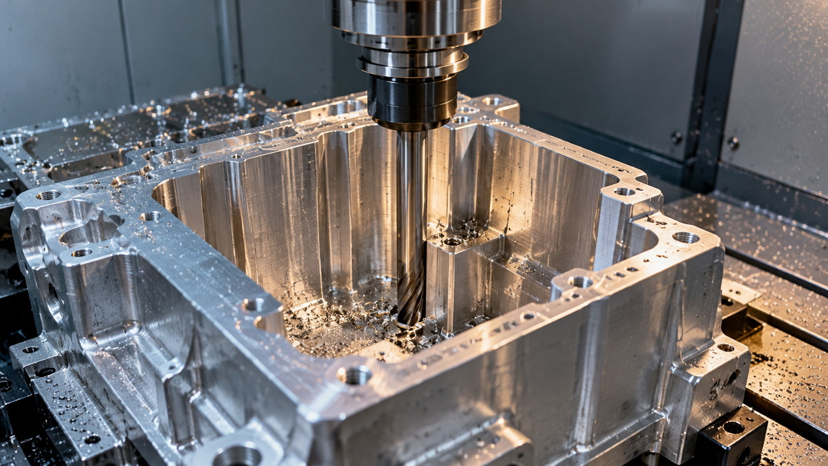
There is no universal depth that makes every pocket difficult. A broad cavity with generous corner radii may be relatively accessible, while a shallower, narrow slot may require a fragile cutter.
Two relationships matter:
- Pocket depth relative to the available opening.
- Required tool overhang relative to tool diameter.
These relationships are connected, but they are not interchangeable. A wide pocket can still require substantial overhang because of holder clearance or surrounding geometry.
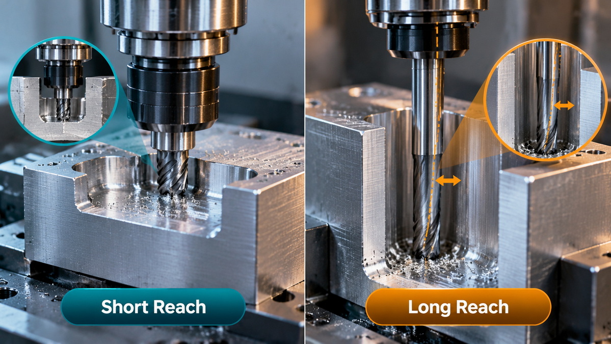
Tooling guidance commonly identifies increased vibration risk as overhang approaches or exceeds approximately four times the tool diameter. This is a planning indicator, not a universal machining limit.
For example, a 40 mm-deep pocket does not automatically require only 40 mm of tool extension. Clearance above the workpiece and interference avoidance may increase the unsupported reach.
The practical lesson is straightforward: evaluate the complete tool assembly, not pocket depth alone.
An end mill behaves approximately like a cantilever: one end is supported, while the cutting end experiences force.
With other variables unchanged, doubling unsupported length increases calculated deflection eightfold.
This relationship explains why a modest increase in reach can create a disproportionate accuracy problem. However, it is an illustration, not a prediction of actual machining error. Flutes, holder stiffness, engagement, and changing cutting forces complicate real behavior.
For deep features, rigidity is often more important than the machine's advertised positioning resolution.
Chatter is self-excited vibration within the machining system. Long tool assemblies and flexible workpiece walls can make it harder to maintain a stable cut.
Its consequences may include:
- Wavy or patterned surfaces.
- Inconsistent wall dimensions.
- Accelerated edge wear.
- Unpredictable tool failure.
- Additional finishing passes.
Reducing cutting speed alone does not guarantee a solution. Tool engagement, spindle speed, holder selection, and workpiece support must work together.
Deep cavities can trap chips near the cutting zone. Recutting those chips increases the risk of edge damage, surface scratching, and unstable cutting.
The difficulty depends on material, cavity shape, toolpath, and machine orientation.
A suitable coolant or air-delivery strategy must actually reach the cutting zone and provide an exit route for chips. More coolant at the pocket opening does not necessarily solve poor evacuation at the bottom.
Sometimes the cutter is not the only flexible component.
As surrounding material disappears, pocket walls may lose support. Cutting forces can push them away from the tool, and clamping can distort the workpiece.
After unclamping, the geometry may change again.
That is why a successful deep-pocket process must consider the part's final free-state condition, rather than relying exclusively on measurements taken while it remains constrained.
Pocket width is only one acceptance requirement. A feature may pass a single width measurement while still having unacceptable taper or form.
| Requirement | Possible deep-pocket problem | What to clarify |
|---|---|---|
| Pocket width | Dimensions change with depth | Measurement locations and size limits |
| Wall perpendicularity | Wall leans relative to its datum | Datum system and orientation control |
| Wall profile | Local bowing or waviness | Required profile tolerance |
| Floor flatness | Floor varies across its area | Controlled surface and support condition |
| Pocket position | Feature shifts relative to mating geometry | Functional datum references |
| Surface texture | Chatter or chip scratches remain | Required finish and evaluation method |
The drawing should identify what the assembly actually needs.
A blanket tight tolerance on every internal surface may add cost without improving function. Conversely, a general size tolerance may not adequately control a sealing wall or precision locating surface.
Do not use maximum reach throughout the entire operation when shorter tools can remove accessible material first.
A staged approach may use:
1. A short, rigid cutter for upper-region roughing.
2. An intermediate-reach tool as depth increases.
3. A long-reach tool only where necessary.
4. A separate finishing strategy for critical surfaces.
This limits the amount of work assigned to the least rigid assembly.
Roughing prioritizes material removal. Finishing prioritizes geometry and surface quality.
Trying to achieve both simultaneously can leave inconsistent stock and expose finishing edges to unnecessary loads.
A controlled sequence leaves planned finishing allowance, removes remaining corner stock, and then finishes under more consistent engagement.
The allowance must suit the material, cutter, and wall stiffness. Too much increases force; too little may create rubbing or inconsistent cutting.
A cutter can experience a sudden load increase when entering a tight internal corner.
Suitable toolpaths reduce abrupt engagement changes and avoid forcing a long tool into excessive contact.
Where appropriate, circular ramping or plunge milling may provide alternatives to conventional side milling. These are application-dependent options, not universally superior methods.
The best choice depends on geometry, machine capability, material, and the direction in which the system can support cutting forces.
A rigid initial setup may become less effective as the part becomes thinner.
Fixture design should account for:
- Support near flexible walls.
- Tool and holder access.
- Clamp locations.
- Distortion from clamping force.
- Inspection after unclamping.
For thin floors or tall walls, machining sequence can matter as much as fixture strength. Excessive clamping is not a substitute for appropriate support.
Small internal radii restrict cutter diameter. A smaller cutter generally offers less bending stiffness and may require slower, more cautious machining.
Allowing a larger radius can open the door to a more rigid tool.
Avoid requiring the cutter radius to match the pocket corner exactly where an alternative geometry is acceptable. Additional clearance can help reduce abrupt engagement during corner finishing.
Before approving a deep cavity, ask:
- Does the entire pocket need its maximum depth?
- Can a local recess replace a full-depth cavity?
- Can the feature be accessed from another direction?
- Could a removable cover or separate component preserve function?
These changes require engineering review. They may affect sealing, strength, assembly, or maintenance.
However, improving access can be more effective than demanding increasingly complex machining from an unchanged design.
Identify which surfaces locate, seal, guide, or contact another component.
Then distinguish those surfaces from clearance areas.
This gives the manufacturing partner more freedom to select practical processes while protecting the dimensions that determine product performance.
Consider a hypothetical aluminum housing with a 50 mm-deep cavity, small internal corners, and a closely controlled wall-to-wall dimension.
This is an engineering illustration, not a documented U-Need customer project.
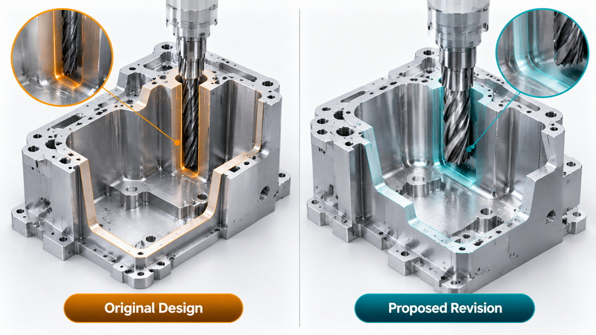
The initial design requires a small-diameter cutter with substantial reach. The likely concerns are tool deflection, corner engagement, and reliable measurement near the cavity floor.
A useful review would investigate three changes:
| Proposed change | Potential benefit | Required check |
|---|---|---|
| Increase selected corner radii | Allows a larger cutter | Mating-component clearance |
| Apply tight control only to locating surfaces | Reduces unnecessary finishing demands | Assembly requirements |
| Add access from a second direction | May shorten effective reach | Structural and sealing implications |
None guarantees a particular cost reduction or tolerance.
The value comes from addressing the source of difficulty before committing to production, rather than attempting to compensate for poor access through slower cutting alone.
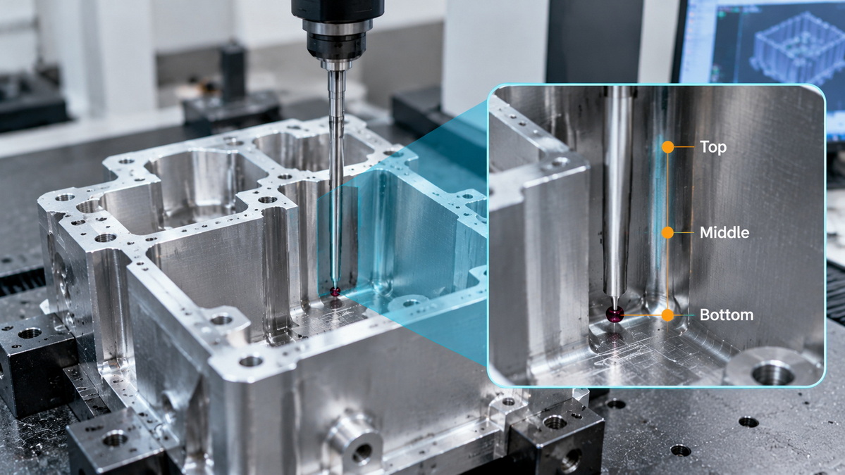
Inspection should be planned before the machining route is finalized.
A measurement near the opening cannot establish that the entire wall is correct.
For critical pockets, consider measurements near the top, middle, and bottom, with additional locations where geometry or process risk justifies them.
The final sampling plan should reflect the drawing and acceptance requirements.
Long styli provide reach but introduce measurement challenges. Probe performance depends on stylus length, configuration, probing direction, qualification, and the complete measuring system.
A coordinate measuring machine's headline accuracy does not automatically establish uncertainty for a specific deep-pocket measurement.
Check access, collision clearance, probe qualification, and whether the selected method can distinguish the expected error from measurement variation.
Where relevant, inspect after unclamping and after specified finishing operations.
For coated parts, establish whether dimensional requirements apply before or after coating. Otherwise, the supplier and buyer may evaluate different conditions while believing they are using the same drawing.
A useful quotation package should include more than a model and material name.
Provide:
1. A dimensioned drawing with functional datums.
2. A matching three-dimensional model and revision.
3. Material grade and required condition.
4. Critical tolerances and surface finishes.
5. Coating or heat-treatment requirements.
6. Prototype and production quantities.
7. Inspection and reporting expectations.
8. Areas where design changes are acceptable.
Ask the supplier to explain the highest-risk feature, proposed tool-access strategy, and intended inspection approach.
A credible review should distinguish demonstrated capability from a proposal that still requires trials.
U-Need supports global brands, distributors, and manufacturers with custom precision parts machining, mold manufacturing, and sheet metal fabrication.
For a deep-pocket machining inquiry, send your drawing, model, material specification, quantity, and critical acceptance requirements.
Request a manufacturability review focused on tool reach, internal radii, wall stability, and inspection access. This creates a clearer basis for discussing achievable tolerances, process options, and quotation assumptions before production begins.
Yes, but feasibility depends on geometry, material, tool access, workholding, and inspection. A tolerance achievable on an accessible surface may require a different process inside a deep cavity.
There is no universal limit. Tooling guidance identifies increased vibration concerns around four times tool diameter in relevant overhang applications. Treat this as a review point, not an automatic pass-or-fail rule.
No. Additional orientations may improve access or shorten tool reach, but they cannot eliminate every interference condition, thin-wall problem, or rigidity limitation. Evaluate the actual geometry rather than machine-axis count alone.
Tool deflection, changing engagement, tool wear, and workpiece movement can contribute. Measurements at multiple depths help distinguish a consistent size offset from taper or local wall distortion.
No. Another pass may remove remaining stock, but it cannot restore material already removed. If unstable cutting or wall movement continues, repeating the same pass may not resolve the underlying problem.
Compare the proposed machining and inspection plans, not only price or nominal machine accuracy. Look for clear assumptions, identified risks, drawing-based acceptance criteria, and evidence appropriate to the requested feature.
The technical discussion draws on the following tooling, design, and metrology resources. The housing example is hypothetical; U-Need's service description comes from the company information supplied for this article.
1. Sandvik Coromant — "Profile Milling." Guidance on long-overhang tooling, staged tool lengths, cutting-force changes, and deep-profile machining. [sandvik.coromant]
2. Sandvik Coromant — "Milling Troubleshooting." Guidance on vibration, excessive overhang, stability, and chip recutting in deep cavities. [sandvik.coromant]
3. Sandvik Coromant — "Milling Holes and Cavities/Pockets." Application guidance covering circular ramping and plunge milling for challenging cavities. [sandvik.coromant]
4. Sandvik Coromant — "How to Reduce Vibration in Milling." Discussion of overhang-related vibration and adapting tooling and cutting conditions. [sandvik.coromant]
5. Protolabs — "CNC Milling: Machining Design Guidelines." Design guidance explaining internal corner radii and milling-tool constraints. [protolabs]
6. Renishaw — "Probe Operation." Explanation of stylus pretravel, qualification, and the influence of long styli on measurement performance. [renishaw]
7. CNC Cookbook — "Deep Pocket, Deep Cavity, & Deep Slot Milling." Practitioner discussion of tool deflection, stickout, cutter diameter, and deep-feature machining. The simplified beam relationship in this article is an explanatory mechanics model, not measured machining-performance data. [cnccookbook]


