Views: 267 Author: U-Need Publish Time: 2026-10-22 Origin: Site
Content Menu
● What Do Accuracy and Repeatability Mean in Small-Hole Machining?
>> Specify More Than Hole Diameter
● What Makes Small Holes Difficult to Machine?
● Seven Factors That Affect Small-Hole Accuracy and Repeatability
>> 1. Tool Runout and Toolholding
>> 2. Tool Length, Rigidity, and Entry Conditions
>> 3. Workpiece Material and Chip Formation
>> 4. Coolant Delivery and Chip Evacuation
>> 5. Cutting Speed, Feed, and Tool Wear
>> 6. Fixturing and Thermal Stability
>> 7. Burrs and Subsequent Operations
● Choosing a Process for Tight-Tolerance Small Holes
● A Practical Workflow for Validating Repeatable Hole Quality
>> Step 1: Review the Drawing and Application
>> Step 2: Select and Document the Process
>> Step 3: Approve the Inspection Method
>> Step 4: Validate Under Production Conditions
>> Step 5: Set Monitoring and Reaction Rules
● How to Measure Small Holes Without Misleading Results
● An Illustrative Troubleshooting Example
● What to Include in a Small-Hole Machining RFQ
>> What tolerance can precision CNC machining achieve on small holes?
>> Does a smaller drill always require higher spindle speed?
>> Can reaming correct a hole drilled in the wrong position?
>> Why do holes change size during a production run?
>> Are deep small holes harder to control than shallow holes?
>> How can a buyer verify repeatability?
Precision CNC machining for small holes requires more than a small drill and a high-speed spindle. Hole diameter, position, straightness, surface condition, and consistency all depend on how the cutting tool, workpiece, machine, coolant, and inspection method work together.
For buyers, the practical question is not simply, "Can this hole be machined?" It is, "Can every critical hole meet the drawing requirements throughout production?"
U-Need supports global brands, distributors, and manufacturers with custom precision parts machining, mold manufacturing, and sheet metal fabrication in China. For components with small, demanding holes, a clear specification and a carefully planned manufacturing route provide the foundation for a productive technical discussion.
This guide explains what affects small-hole accuracy, how repeatability differs from accuracy, and what buyers should confirm before approving production.

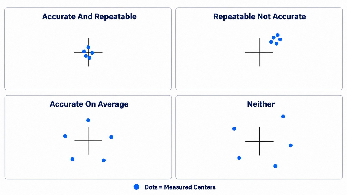
Accuracy describes how closely a measured feature matches its specified requirement. Repeatability describes how consistently a process produces similar results under defined conditions.
A process can be repeatable without being accurate. For example, holes may consistently measure larger than the drawing allows. Conversely, one acceptable first article does not prove that subsequent holes will remain within tolerance.
Small-hole requirements may include:
| Requirement | What it controls | Why it matters |
|---|---|---|
| Diameter | Hole size | Fit, clearance, or flow |
| Position | Location relative to datums | Alignment and assembly |
| Roundness | Circular form at a section | Contact and sealing |
| Cylindricity | Overall cylindrical form | Consistent engagement |
| Straightness | Deviation along the hole | Passage or component alignment |
| Surface texture | Internal surface condition | Friction, wear, or sealing |
| Burr condition | Material remaining at edges | Assembly cleanliness and function |
These characteristics are not interchangeable. A hole can pass a diameter check while failing its position or form requirements.
The most useful starting point is therefore function: what must the hole do in the finished assembly?
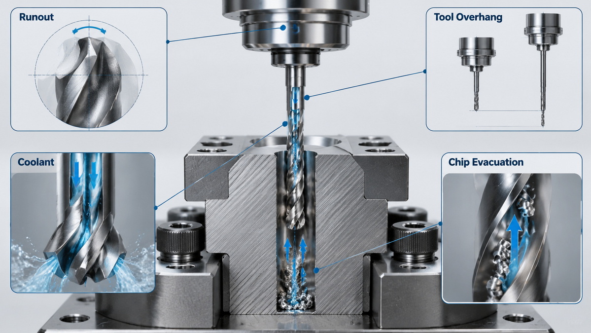
As drill diameter decreases, the cutting tool becomes more sensitive to runout, deflection, chip obstruction, and handling damage. Small process disturbances can consume a significant share of the available tolerance.
Depth adds another challenge. Consider two illustrative holes:
- A 1 mm diameter hole with a depth of 2 mm has a depth-to-diameter ratio of 2:1.
- A 1 mm diameter hole with a depth of 10 mm has a ratio of 10:1.
The second hole creates a longer path for chips and coolant. It also requires a longer cutting tool, increasing the importance of guidance and stability.
There is no universal diameter below which all holes become "micro holes." Tool suppliers use application-specific terminology. For purchasing decisions, actual diameter, depth, material, and tolerances are more useful than the label.
Runout means the rotating cutting tool does not follow its intended rotational axis precisely. Excessive runout can create uneven cutting loads, accelerate wear, and affect hole size and form.
For small-diameter tools, inspect the complete assembly:
- Spindle interface and cleanliness.
- Holder condition.
- Collet compatibility.
- Tool seating.
- Cutting-edge condition.
- Tool projection.
Measure runout with the tool installed, using an appropriate method and location. A holder's catalog specification does not establish the actual runout of the assembled cutting system.
Avoid treating one published runout limit as suitable for every small-hole application. The acceptable value depends on the tool, diameter, material, and required result.
A longer drill is generally more vulnerable to deflection than a shorter, otherwise comparable tool.
Use the shortest practical tool that can reach the required depth and clear the component safely. Deep-hole applications may require a dedicated pilot-drilling sequence specified by the tool manufacturer.
Entry geometry also matters. Inclined surfaces, curved faces, and interrupted entries can load the cutting edges unevenly.
Depending on the design, a stable entry may require a prepared flat, a compatible pilot hole, or a specialized drill. Spotting should not be added automatically; confirm compatibility with the selected drill geometry.
Material behavior influences cutting forces, heat, chip shape, and tool wear.
Ductile materials may generate chips that are difficult to evacuate. Some alloys are sensitive to work hardening. Abrasive materials can accelerate cutting-edge wear.
Material identification should include more than a broad family name. Specify the alloy or grade, heat-treatment condition, and relevant hardness requirements.
For repeat production, material consistency matters too. A process established on one material condition should not be assumed to perform identically after a significant change in hardness or supply condition.
Coolant helps manage heat and move chips away from the cutting zone. In a small hole, a blocked flute can rapidly destabilize the process.
Review:
- Whether coolant reaches the cutting edges.
- External versus through-tool delivery.
- Pressure and flow requirements.
- Filtration and coolant concentration.
- Drill-channel availability at the chosen diameter.
More pressure is not automatically better. Requirements differ between tool designs and applications. Follow the selected tool's guidance rather than copying a pressure value from an unrelated drilling operation.
Likewise, peck drilling is not a universal solution. Some tools require specific entry, feed, and retraction strategies.
Spindle speed alone does not determine hole quality. Feed, cutting speed, drill geometry, coating, material, and coolant must form a compatible cutting system.
An unsuitable feed can increase cutting loads or produce ineffective cutting. Worn or damaged edges can change hole size, surface condition, and burr formation.
For repeatability, establish a tool-life policy before quality becomes unpredictable. This may use a validated hole count, inspection results, wear observations, or a combination.
A tool should not remain in production merely because it has not broken.
A rigid machine cannot compensate for a moving or distorted workpiece.
Locate and support the component close enough to the cutting area to limit movement. However, excessive clamping can deform thin sections and change the geometry after release.
Thermal conditions also influence dimensions. Machine warm-up, spindle operation, coolant temperature, and changes in the surrounding environment can contribute to drift.
A realistic validation should include the intended production cycle, not just isolated holes made under unusually favorable conditions.
Hole quality is not complete when the drill retracts. Exit burrs, intersecting passages, coatings, and later processing can affect the finished feature.
Blind holes and cross-holes deserve particular attention because internal burrs may be difficult to access.
Define the required edge condition and confirm when inspection occurs. If plating, heat treatment, or another operation can change the final feature, establish acceptance requirements for the appropriate manufacturing stage.
Drilling may produce a finished hole, but some requirements call for additional operations or another manufacturing route.
| Process | Potential application | Important limitation |
|---|---|---|
| Drilling | Producing the initial hole or a finished feature | Capability depends on geometry and conditions |
| Reaming | Refining diameter and surface condition | Does not reliably correct substantial location error |
| Boring | Adjusting size and location where access allows | Very small diameters restrict tool rigidity |
| Hole milling | Producing holes through controlled toolpaths | Limited by cutter size, access, and machine capability |
| EDM hole drilling | Certain small or deep holes in conductive materials | Surface condition and subsequent requirements need review |
The right choice depends on which characteristic is difficult to achieve.
For example, adding reaming may help a size requirement but leave an unacceptable positional error unresolved. Process planning should address the actual failure mode rather than simply add a finishing operation.
A controlled validation sequence is more informative than a single inspection report.
Confirm diameter, tolerance, depth, hole type, datums, positional requirements, surface condition, and burr limits.
Identify whether the hole supports assembly, fluid flow, alignment, or another function. This helps distinguish critical requirements from unnecessarily restrictive callouts.
Record the intended tooling, holder, cutting conditions, coolant arrangement, fixture, and finishing sequence.
Documentation makes later troubleshooting more meaningful. Without it, a successful trial can be difficult to reproduce.
Select measurement equipment before committing to a manufacturing route.
Check accessibility, resolution, calibration, uncertainty, and the characteristics each method can actually assess.
Inspect features across a representative sequence rather than relying only on the first acceptable component.
Where relevant, include normal warm-up behavior, tool changes, interruptions, and reclamping. Record measurements in production order so gradual drift remains visible.
Define what happens when measurements approach a limit, burrs increase, or the tool reaches its approved life.
A useful control plan identifies when to stop, inspect, replace tooling, and review potentially affected parts.
Measurement can become the limiting factor when holes are small, deep, or inaccessible.
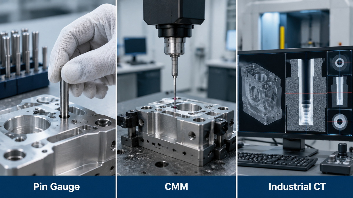
A pin gauge can help assess size acceptance, but it does not provide a complete description of roundness, taper, or position. Likewise, measuring a visible entrance does not necessarily establish the condition deeper inside the hole.
Depending on the feature, inspection may involve:
- Calibrated pin gauges.
- Suitable bore-measuring equipment.
- Coordinate measurement with appropriately sized probes.
- Optical measurement for accessible features.
- Industrial computed tomography for internal geometry.
Industrial CT can inspect internal structures without sectioning the component. However, suitability depends on material, geometry, scanning conditions, and demonstrated measurement capability. It should not be presented as automatically adequate for every tight tolerance.
Agree on the measurement strategy with the supplier before production. Different measurement methods can otherwise create disputes about the same component.
Consider a hypothetical small through-hole in a stainless-steel component. Early parts pass inspection, but later parts show larger entrance diameters and increased exit burrs.
Several explanations are possible:
1. Cutting-edge wear is changing the cutting action.
2. Runout or holder contamination is producing uneven loading.
3. Chip evacuation is deteriorating.
4. Workpiece support or thermal conditions are changing.
5. The measurement method is responding inconsistently to burrs.
The investigation should compare production-order measurements with tool condition, runout checks, coolant delivery, and burr observations.
Changing spindle speed immediately may obscure the original cause. A controlled comparison is more useful than changing several variables together.
This example illustrates a diagnostic approach, not a reported customer result or a guaranteed manufacturing outcome.
A complete request for quotation helps suppliers evaluate feasibility and identify cost drivers.
Provide:
- A dimensioned drawing and relevant 3D model.
- Material grade and condition.
- Hole diameter, depth, and quantity per component.
- Through-hole, blind-hole, and intersecting-hole details.
- Datums and geometric tolerances.
- Surface finish and edge requirements.
- Post-machining treatments.
- Order quantity and expected repeat demand.
- Inspection and documentation requirements.
Ask which operations establish the critical characteristics, how they will be measured, and how production consistency will be monitored.
For a U-Need quotation, submit the drawing, material specification, quantities, and critical-hole requirements. Request a review of the proposed manufacturing route and inspection approach before approving production. Projects combining machined parts, molds, or sheet metal components should identify the interfaces between those components as well.
There is no responsible universal figure. Achievable tolerance depends on diameter, depth, material, tooling, finishing operations, thermal conditions, and inspection capability. A supplier should evaluate the actual feature.
Not automatically. Required speed follows the selected cutting speed and tool diameter, but practical settings must also respect tool guidance, material behavior, spindle capability, and stability.
Reaming generally follows the existing hole. It can refine size and surface condition, but it should not be relied on to correct substantial positional error.
Possible causes include tool wear, thermal drift, changing runout, chip buildup, material variation, and measurement inconsistency. Measurements recorded in production order help identify patterns.
Generally, yes. Greater depth increases the demands on tool stability, chip evacuation, coolant access, and inspection. The depth-to-diameter ratio is an important planning parameter.
Request results from a representative production sequence, not only a first article. Confirm the measurement method, sampling plan, tool-life controls, and response to dimensional drift.
1.Sandvik Coromant. "Drilling." Technical guidance covering drill selection, hole quality, runout, and coolant considerations. [Read the technical guide]. [sandvik.coromant]
2.Sandvik Coromant. "Drilling Wear and Troubleshooting." Diagnostic guidance for hole form, tool wear, chip jamming, and unstable cutting conditions. [Read the troubleshooting guide]. [sandvik.coromant]
3.Sandvik Coromant. "CoroDrill® Dura 462." Product-specific guidance on pilot drilling, tool runout, and coolant delivery. Its numerical recommendations should not be generalized to unrelated tools. [Read the application guidance]. [sandvik.coromant]
4.Haas Automation. "CNC Accuracy and Thermal Growth." Service checklist addressing dimensional variation, operating conditions, and thermal influences. [Read the technical checklist]. [haascnc]
5.ZEISS Industrial Quality Solutions. "CT Measuring Services." Overview of nondestructive inspection and measurement of internal and external component geometry. [Read the measurement overview]. [zeiss]


