Views: 255 Author: U-Need Publish Time: 2026-10-11 Origin: Site
Content Menu
● High-Tolerance CNC Precision Parts vs Manufacturing Capability: The Core Difference
● How to Define CNC Machining Tolerances Around Part Function
>> Separate Critical Features From General Dimensions
>> Specify Geometry, Not Just Size
● How Manufacturing Capability Changes With the Machine Process
>> CNC Milling: Geometry and Setup Relationships Matter
>> CNC Turning: Match the Process to Rotational Features
>> Reaming, Grinding, and Other Finishing Operations
● Why Published CNC Tolerance Numbers Need Context
● Process Capability: What Cp and Cpk Actually Tell Buyers
>> An Illustrative Capability Example
>> Ask Whether the Study Represents Production
● The Hidden Precision Budget: Heat, Workholding, and Measurement
>> Thermal Behavior Can Change the Result
>> Inspect the Part in Its Relevant Condition
>> Measurement Resolution Is Not Measurement Certainty
● A Practical Tolerance-Matching Workflow
>> Step 1: Establish the Functional Requirement
>> Step 2: Review the Tolerance Stack
>> Step 3: Assign Critical Features to Operations
>> Step 4: Confirm the Final Acceptance Condition
>> Step 5: Validate and Agree on Change Control
● Illustrative Industry Scenario: A Precision Bore in a Lightweight Housing
● How U-Need Fits Into the Manufacturing Decision
>> What Does "High-Tolerance CNC Precision Parts" Mean?
>> Is a More Advanced CNC Machine Enough to Guarantee Tolerance?
>> Can One Passing Prototype Prove Manufacturing Capability?
>> Should Every Feature Have the Tightest Possible Tolerance?
>> When Should Grinding or Reaming Be Considered?
>> Should Critical Dimensions Be Checked After Coating?
● Start With a Feature-Specific Manufacturing Review
High-tolerance CNC precision parts and manufacturing capability must be evaluated together. A drawing defines the acceptable variation; the manufacturing process determines whether that variation can be maintained reliably. The right tolerance is therefore not the smallest number a machine can occasionally achieve. It is the requirement that protects part function and can be produced, measured, and repeated economically.
For global brands, distributors, and manufacturers sourcing custom precision parts, this distinction affects assembly performance, purchasing costs, and delivery risk.
My starting point when reviewing a precision-part specification is simple: identify what must fit, move, seal, or locate before deciding how tightly every feature should be controlled.
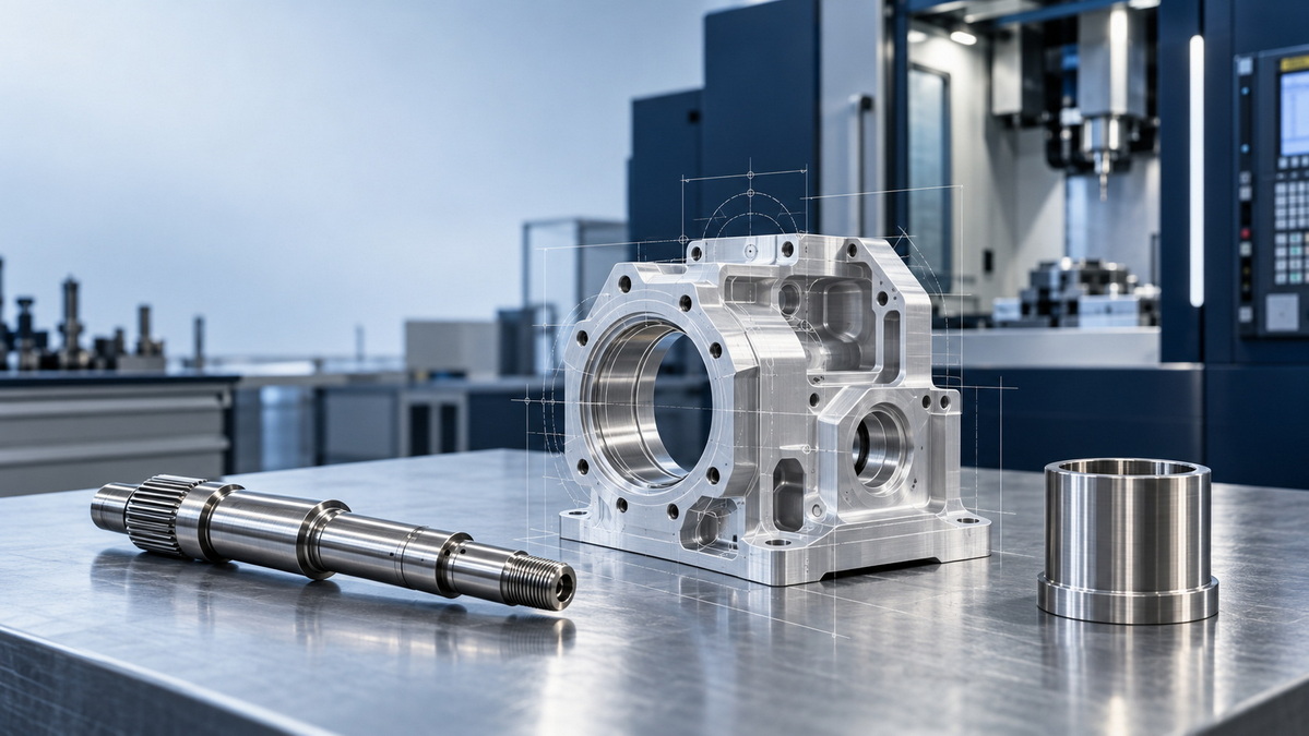
Tight-tolerance CNC precision parts describe an output requirement. Manufacturing capability describes the process's demonstrated ability to meet that requirement.
These are complementary concepts, not competing alternatives.
| Comparison factor | Tight-tolerance precision parts | Manufacturing capability |
|---|---|---|
| Main question | What variation can the design accept? | What variation can the process consistently deliver? |
| Defined through | Dimensions, limits, geometric controls | Production data and process conditions |
| Primary concern | Fit, function, interchangeability | Stability, repeatability, verification |
| Supporting evidence | Engineering drawings and assembly requirements | Inspection records and capability studies |
| Main risk | Specifying unnecessary precision | Promising precision without repeatable evidence |
A conforming prototype demonstrates that one part meets the drawing. It does not establish that future batches will behave the same way.
The central purchasing principle is repeatability: evaluate the production route, not just the best sample.
Not every feature needs identical precision.
A bearing seat may require close dimensional control. An external cover surface may tolerate considerably more variation. Applying the bearing-seat tolerance throughout the part can increase machining and inspection effort without improving performance.
Classify features by their purpose:
- Mating features: shafts, bores, sliding interfaces, and locating pins.
- Alignment features: mounting holes and reference surfaces.
- Sealing features: grooves and contact faces.
- Noncritical features: clearance pockets and cosmetic boundaries.
This classification gives the supplier a practical basis for selecting machining operations.
A bore can meet its diameter limits yet fail assembly because its axis is incorrectly located.
Likewise, a mounting face can meet a thickness dimension while lacking the required flatness.
Geometric dimensioning and tolerancing, commonly called GD&T, communicates requirements for form, orientation, location, and runout. Datum references establish the relationship between relevant features.
Specify the drawing standard and edition. Manufacturing and inspection teams need the same interpretation, especially when parts move between suppliers or countries.
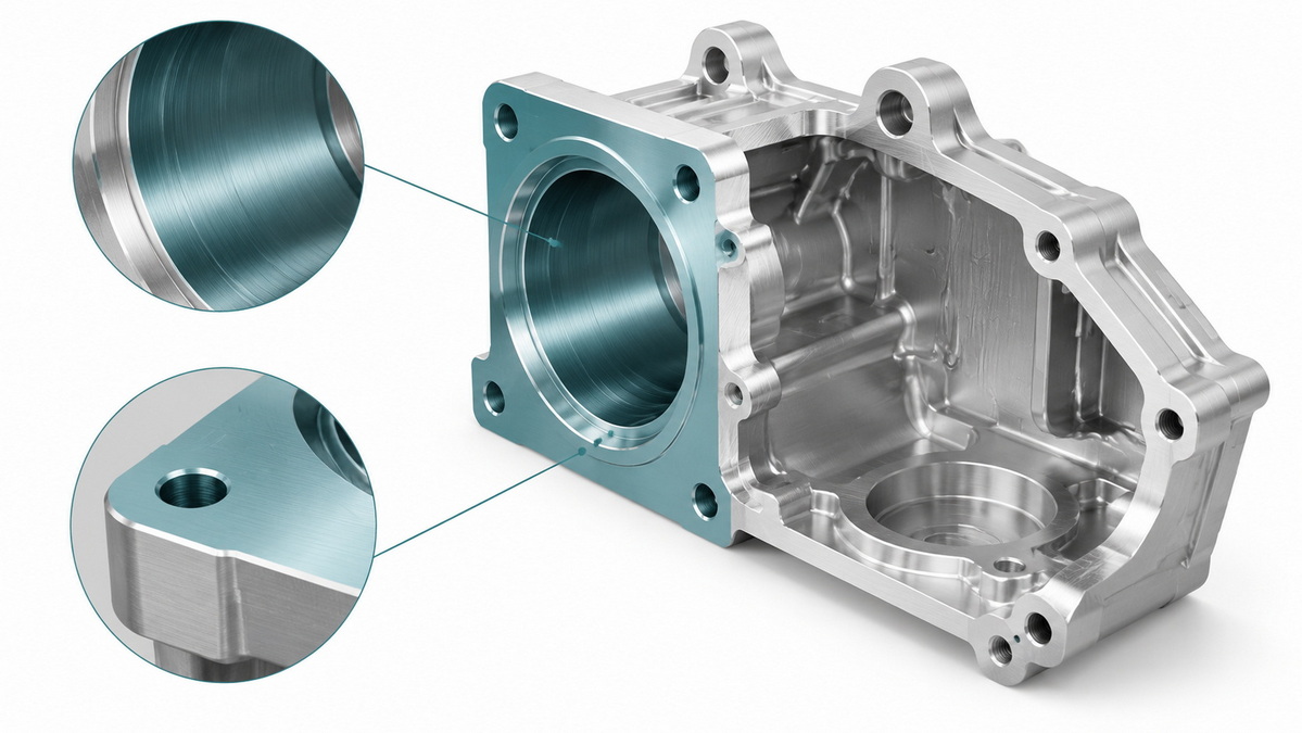
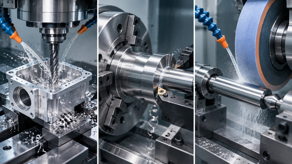
CNC milling is suitable for pockets, faces, slots, and complex prismatic geometry. However, feature accessibility and machining sequence influence the process.
A short, accessible pocket presents a different challenge from a deep cavity requiring a slender cutter. Repositioning a part also introduces another opportunity for locating variation.
Where practical, machine related critical features in the same setup. If multiple setups are necessary, define how their datum relationships will be maintained.
CNC turning is a logical starting point for shafts, sleeves, and other rotational components.
Producing related diameters in one setup can simplify their geometric relationship. Nevertheless, part length, support conditions, clamping, and material behavior still matter.
A short sleeve and a long slender shaft should not receive the same capability assumption merely because both are turned.
When a critical feature exceeds the validated capability of the initial machining operation, the solution may be a different finishing process.
Reaming can be considered for controlled hole size. Grinding may be considered for selected hardened surfaces or demanding dimensional requirements.
These operations are not automatic guarantees. They need suitable stock allowance, tooling, access, and inspection.
| Feature requirement | Process route to evaluate | Key limitation to investigate |
|---|---|---|
| General pockets and faces | CNC milling | Access, deflection, setup |
| Rotational mating surfaces | CNC turning | Support and clamping |
| Closely controlled hole size | Boring or reaming | Hole preparation and geometry |
| Selected hardened precision surfaces | Grinding | Distortion and finishing allowance |
| Related features across several faces | Indexed or multi-axis machining | Datum transfer and access |
The strongest process plan assigns an operation to each critical feature rather than labeling the entire part "high precision."
Published tolerance ranges are useful for screening suppliers, but they are not universal manufacturing limits.
For example, Protolabs publishes ±0.005 in. (approximately ±0.13 mm) for one standard machining offering, ±0.002 in. (approximately ±0.051 mm) for a precision offering, and ±0.0005 in. (±0.0127 mm) for eligible reamed holes.
These figures describe specific service conditions. They are not U-Need specifications or guarantees for every geometry.
Before comparing quotations, check:
1. Which features receive the quoted tolerance?
2. Does it apply to size, location, or both?
3. Which materials and dimensions are covered?
4. Does inspection occur before or after finishing?
5. Is the requirement validated for the intended production quantity?
A supplier's headline tolerance is less informative than a feature-specific response to your drawing.
Capability analysis compares process variation with specification limits.
Here, USL and LSL are the upper and lower specification limits, \(\mu\) is the process mean, and \(\sigma\) represents process standard deviation.
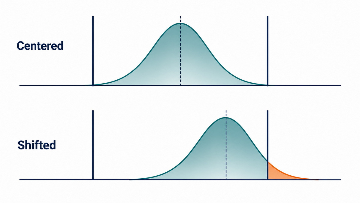
Cp compares the specification width with process spread. Cpk also considers whether the process is centered.
Consider a hypothetical shaft specified at 20.000 ±0.010 mm.
If the stable process mean is 20.000 mm and its standard deviation is 0.002 mm:
- The total tolerance width is 0.020 mm.
- Cp is approximately 1.67.
- Cpk is approximately 1.67.
If the mean shifts to 20.004 mm while variation remains unchanged, Cp stays approximately 1.67, but Cpk falls to 1.00.
The process spread has not changed. Its position within the tolerance window has.
These are illustrative calculations, not U-Need production results.
NIST explains that capability analysis concerns an in-control process. Conventional capability indices also rely on distribution assumptions and adequate independent observations; its guidance identifies roughly 50 observations as a generally useful minimum for estimates.
A handful of selected samples cannot establish dependable capability.
Ask whether the data represent relevant tooling, setups, material batches, and operating conditions. Agree on the acceptance target before production rather than treating any single Cpk value as universally mandatory.
Machine thermal growth is a recognized source of machining inaccuracy. Haas publishes dedicated procedures for investigating it.
A process qualified under one thermal condition may behave differently during extended operation.
For demanding features, discuss warm-up conditions, operating cycles, and when dimensions are checked. Avoid assuming that one successful first-piece inspection represents the entire run.
Workholding must secure the component without creating unacceptable deformation.
For a thin-walled component, the important question is not simply whether the dimension passes while clamped. It is whether the released part meets its functional requirements.
The inspection plan should define the condition in which the drawing applies.
A digital instrument displaying small increments does not necessarily establish equally small measurement uncertainty.
NIST defines uncertainty as a parameter associated with the measurement result that characterizes the dispersion of values reasonably attributable to the measured quantity.
For tight-tolerance CNC parts, agree on:
- Measurement method and datum alignment.
- Equipment calibration and suitability.
- Relevant environmental conditions.
- Treatment of results close to specification limits.
Manufacturing capability and measurement capability must support each other.
Identify the failure you are preventing: interference, leakage, misalignment, vibration, or inadequate clearance.
Describe the requirement at assembly level before assigning individual dimensions.
Several acceptable components can still produce an unacceptable assembly.
Use worst-case analysis where guaranteed limits are necessary. Consider statistical methods only when their assumptions and assembly risks are justified.
Create a feature-to-process matrix covering rough machining, finishing, heat treatment, coating, and inspection.
This makes hidden process dependencies visible before purchasing.
Specify whether critical dimensions apply before or after surface treatment.
Anodizing can change dimensions through oxide formation and pretreatment. The net effect depends on the process, alloy, and treatment specification.
Do not apply one universal dimensional allowance to every anodized part.
Review representative inspection data before releasing repeat production.
Define what requires revalidation: a material substitution, fixture change, machine transfer, or revised finishing operation may affect previously demonstrated performance.
Consider a hypothetical aluminum housing with a locating bore and several external pockets.
Applying an equally tight tolerance everywhere would not necessarily improve the locating function.
A more targeted review would:
1. Define bore size and position relative to functional datums.
2. Retain suitable general tolerances on nonmating pockets.
3. Evaluate a dedicated bore-finishing operation.
4. Check whether clamping affects the released housing.
5. Confirm the bore's acceptance condition after surface treatment.
The value comes from connecting design intent, process selection, and inspection—not from tightening every dimension.
This is an engineering illustration, not a reported customer project.
U-Need is a precision manufacturing partner in China serving global brands, distributors, and manufacturers.
Its stated service scope includes custom precision parts machining, mold manufacturing—including injection molds, stamping dies, and cold-forging dies—and sheet metal fabrication through laser cutting, bending, and stamping.
That breadth supports a useful discussion: should the component remain fully machined, or should another manufacturing route be evaluated alongside secondary precision machining?
The answer depends on geometry, material, volume, tooling investment, and critical features.
A productive quotation request should include:
- A 3D model and controlled 2D drawing.
- Material grade and treatment requirements.
- Critical dimensions and datum references.
- Prototype and expected production quantities.
- Required inspection documentation.
- Final finishing and acceptance conditions.
The phrase commonly describes parts requiring tight dimensional or geometric control. "Tight-tolerance CNC precision parts" is more technically clear because a smaller tolerance permits less variation.
No. Finished-part performance also depends on tooling, workholding, material, thermal behavior, machining sequence, and inspection. Evaluate the complete process rather than machine specifications alone.
No. It proves that the inspected prototype conforms. Repeat-production capability requires representative data from a stable process under relevant conditions.
No. Apply demanding controls where function requires them. Unnecessary precision can add operations and inspection effort without improving assembly performance.
Consider a finishing operation when the critical feature cannot be reliably produced by the proposed initial route. Confirm its suitability for the material, geometry, and acceptance requirement.
When the drawing requires compliance in the finished condition, inspection must address that condition. Agree on masking, allowances, and final verification before machining begins.
Send U-Need your model, drawing, material specification, annual quantity, and critical-feature requirements. Request a feature-by-feature review of the proposed process route, finishing sequence, and inspection approach before approving production.
The objective is reliable functional precision—not unnecessarily restrictive dimensions.
1. [NIST/SEMATECH — "6.1.6. What Is Process Capability?"]. Definitions, Cp/Cpk formulas, stability, sample-size guidance, and distribution assumptions. [itl.nist]
2. [ASME — "Y14.5: Dimensioning and Tolerancing."]. Drawing-language requirements, geometric controls, and datum references. [asme]
3. [Protolabs — "Understanding CNC Machining Tolerances."]. Supplier-specific machining and reamed-hole tolerance examples. [protolabs]
4. [Haas Automation — "Mill: Thermal Growth Test Procedure, AD0815."]. Thermal-growth investigation for machining inaccuracy. [haascnc]
5. [NIST — "Measurement Uncertainty."]. Definition and interpretation of uncertainty in measurement results. [nist]
6. [MPP Group — "Anodizing Tolerances," technical datasheet.]. Dimensional effects of oxide growth and pretreatment, with process-dependent limitations. [mppgroup]


