Views: 231 Author: U-Need Publish Time: 2026-10-11 Origin: Site
Content Menu
● Precision CNC Parts vs Assembly Tolerances: The Essential Comparison
● Why Accurate CNC Parts Can Still Produce Poor Assemblies
>> Individual Tolerances Accumulate Across Multiple Components
>> Correct Feature Sizes Do Not Guarantee Correct Relationships
>> The Inspection Setup May Not Reflect the Assembly
● CNC Part Accuracy, Repeatability, and Functional Fit
● Assembly Tolerance Stack-Up: A Practical Worked Example
>> Root Sum Square Tolerance Analysis
● Functional Datums and GD&T: Connecting Parts to Assembly Requirements
>> Select Datums from the Assembly Interfaces
>> Apply Controls to the Actual Failure Mode
● Hidden Contributors Beyond the CNC Drawing
>> Surface Finishes and Coatings Change Interfaces
>> Temperature Can Change Clearance
>> Clamping and Fastening Can Change Geometry
● An Assembly-First Tolerance Review Workflow
>> 1. Define Measurable Functional Outcomes
>> 2. Map the Critical Tolerance Paths
>> 3. Allocate Tolerances by Sensitivity and Capability
>> 4. Align Drawing Interpretation Before Production
>> 5. Validate Representative Assemblies
>> 6. Update the Specification from Evidence
● Mixed-Process Assemblies: Where Coordination Matters Most
● Control Total Assembly Cost, Not Just Machining Cost
>> Can Precision CNC Parts Fail Assembly Even When They Pass Inspection?
>> Are Assembly Tolerances Always Tighter Than Part Tolerances?
>> Should Every Dimension Receive a Tight Machining Tolerance?
>> When Is RSS Tolerance Analysis Appropriate?
>> What Should Buyers Send for an Assembly-Focused Review?
● Discuss Your Precision Parts and Assembly Requirements with U-Need
Precision CNC parts and assembly tolerances are closely connected, but they answer different engineering questions. Part accuracy asks whether an individual component matches its drawing. Assembly tolerances ask whether interacting components will fit, align, move, and perform correctly together. A shaft, housing, and spacer can each pass inspection while the completed mechanism still binds or develops excessive clearance.
Assembly performance depends on more than accurate machining. It also depends on tolerance stack-up, functional datums, geometric relationships, surface conditions, and operating loads.
My starting question when reviewing a manufacturing drawing is therefore not simply, "How tightly can this feature be machined?" It is, "Which variation could stop the assembly from working?" That shift helps buyers specify precision where it creates value rather than tightening every dimension indiscriminately.
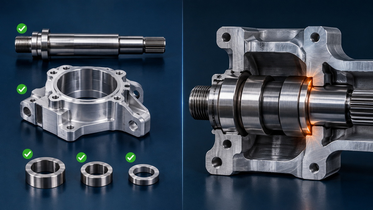
Precision CNC parts are individual components manufactured to defined dimensional, geometric, and surface requirements. Assembly tolerances describe the permissible variation in relationships between components, such as clearance, interference, alignment, or accumulated length.
| Comparison point | Precision CNC parts | Assembly tolerances |
|---|---|---|
| Primary focus | Individual component conformity | Combined functional performance |
| Typical requirements | Diameter, thickness, flatness, position | Clearance, preload, alignment, travel |
| Main reference | Component drawing and datum system | Assembly interfaces and functional requirements |
| Verification | Dimensional and geometric inspection | Stack-up analysis and functional testing |
| Common failure | A feature exceeds its specified limit | Acceptable components produce an unacceptable combination |
| Improvement approach | Correct the relevant manufacturing variation | Review interacting dimensions, geometry, and assembly conditions |
These are complementary controls, not competing approaches. Accurate parts support reliable assemblies only when their specifications correctly express the relationships that matter.
For purchasing teams, "all parts passed inspection" should describe component acceptance—not automatically prove system performance.
Every controlled dimension permits some variation. When several dimensions contribute to one functional gap, their deviations can reinforce one another.
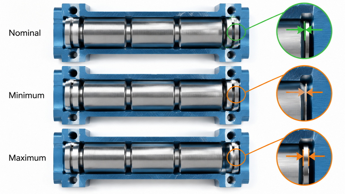
Consider a spacer stack inside a housing. The housing may be near its minimum acceptable length while every spacer is near its maximum. Each item remains compliant, but the available clearance disappears.
The problem is not necessarily poor machining. It may be a tolerance allocation that never protected the assembly requirement.
A hole can have the correct diameter while its axis is incorrectly positioned relative to another hole. A mounting face can meet its thickness requirement while insufficient flatness prevents stable seating.
Dimensional tolerances control size. Geometric controls can address form, orientation, location, and runout.
For precision CNC machining, this distinction matters whenever parts must rotate together, seal against each other, or locate through mating features.
A component may be measured from a convenient inspection reference but installed against a different functional surface.
That mismatch can obscure the relationship responsible for assembly alignment. Inspection should establish the datum reference frame required by the drawing, while that drawing should reflect how the component functions.
A coordinate measuring machine does not compensate for an unsuitable datum strategy. It measures the requirements and setup it receives.
Accuracy describes closeness to the intended value. Repeatability describes consistency across repeated outcomes. Neither alone guarantees functional fit.
A process can repeatedly produce dimensions near one specification limit. Those parts may remain acceptable individually, yet their combination can shift an assembly toward an unfavorable clearance.
Similarly, two mating components should not automatically receive identical tolerances.
A shaft and bore require limits selected for the intended fit:
- Clearance fits permit a specified amount of space between mating features.
- Interference fits create dimensional overlap before assembly.
- Transition fits may produce clearance or interference, depending on actual sizes.
The appropriate choice depends on function. Bearing interfaces, for example, also require consideration of loading, seat geometry, and application conditions. A generic "tight tolerance" instruction cannot replace interface-specific engineering.
The following example is illustrative, not a reported U-Need customer project.
Suppose an assembly contains three rigid spacers inside a housing:
- Housing internal length: \(30.10 \pm 0.03\) mm.
- Each spacer thickness: \(10.00 \pm 0.02\) mm.
- Required total clearance: 0.04–0.16 mm.
Every component can satisfy its drawing while the assembly falls outside the required 0.04–0.16 mm range.
Possible corrections include tightening selected contributors, reducing the number of stacked interfaces, or introducing an adjustable spacer. The best choice depends on cost, interchangeability, and functional risk.
That result is not a guaranteed limit. Correlated dimensions, process drift, or unsupported distribution assumptions can invalidate it.
Use worst-case analysis when the design must accommodate every permitted combination within the model. Use statistical analysis when production evidence supports its assumptions and the acceptance risk is understood.
Geometric dimensioning and tolerancing, commonly called GD&T, communicates permissible geometric variation.
Its value comes from linking requirements to function—not simply adding more symbols.
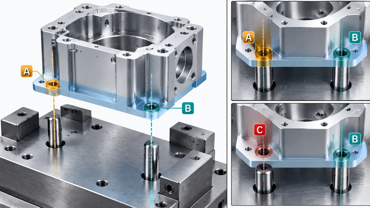
For a mounted housing, a functional datum arrangement might reference:
1. The mounting face that establishes seating.
2. A locating feature that establishes lateral position.
3. Another feature that controls the remaining orientation.
This is an illustrative arrangement, not a universal template. Datum selection depends on actual contact and locating conditions.
The machining setup, drawing, and inspection method should preserve the relationships that the assembly needs.
Relevant controls may include:
- Flatness for seating or sealing surfaces.
- Position for locating holes and interface patterns.
- Perpendicularity for features requiring angular alignment.
- Parallelism for opposing guide surfaces.
- Runout for rotating surfaces relative to a datum axis.
Do not assume that a tight diameter tolerance also controls all relevant geometric errors. Equally, do not add every available control without a functional reason.
Coatings, plating, burrs, and surface texture can affect mating behavior.
Drawings should specify whether acceptance applies before or after finishing. For a bore, coating buildup can reduce the opening; on an external shaft, it can increase the mating size.
Uncontrolled edge burrs may also prevent seating even when the measured feature dimensions comply.
Parts inspected under one temperature condition may operate under another. Different materials and temperature distributions can change their relative dimensions.
For a critical interface, review operating temperatures and material behavior rather than relying exclusively on room-temperature measurements.
Thin walls and compliant components can deform during machining, inspection, or assembly.
A sheet metal bracket may locate differently after fastening than it does in a free-state inspection fixture. Fastener torque and tightening sequence may therefore influence the final relationship.
Where deformation matters, define the relevant inspection state and assembly conditions instead of leaving them implicit.
Replace "must fit correctly" with specific acceptance criteria:
- Permissible clearance or interference.
- Maximum alignment error.
- Required movement or insertion force.
- Allowable runout.
- Relevant operating conditions.
These criteria provide the basis for component requirements.
Identify every dimension and interface contributing to each outcome.
Include purchased components, locating features, coatings, and compliant elements where relevant. Do not analyze only the dimensions controlled by the CNC supplier.
Determine which contributors most strongly affect function. Tighten those requirements where justified, rather than applying uniform precision everywhere.
Ask how critical features will be manufactured and verified. A tolerance without a practical verification method creates avoidable disagreement.
Confirm datum references, finish conditions, measurement methods, and assembly acceptance criteria.
For projects involving multiple suppliers, this coordination is especially important. Each supplier can otherwise optimize its own component while missing the shared interface requirement.
Prototype inspection should include both component conformity and functional testing.
Where practical, evaluate challenging dimensional combinations rather than only a favorable sample set. Record actual measurements so failures can be traced to specific contributors.
Use validation results to correct the tolerance model, inspection plan, or interface design.
The goal is not merely to make one prototype work. It is to establish requirements that support repeatable production and appropriate interchangeability.
U-Need's stated services span custom precision parts machining, mold manufacturing, and sheet metal fabrication. That breadth is relevant when an assembly combines components made through different processes.
Consider a machined bearing block mounted to a bent sheet metal bracket. The block's hole pattern may be accurate, but bracket variation can still alter the final alignment.
The engineering question becomes: which component establishes position, and which should accommodate remaining variation?
Possible design responses include dedicated locating features, controlled interface surfaces, or adjustment where the product permits it. Slots may accommodate variation, but they do not independently establish precise location.
These are design options—not evidence of a particular U-Need process capability. Project-specific feasibility and verification should be confirmed during technical review.

The lowest-priced component is not always the lowest-cost manufacturing solution.
A loosely specified interface can transfer cost into manual fitting, sorting, rework, and assembly troubleshooting. Conversely, unnecessarily tight tolerances can increase manufacturing and inspection effort without improving function.
A useful review compares:
- Component manufacturing cost.
- Inspection effort.
- Assembly labor.
- Rework and rejection exposure.
- Interchangeability requirements.
- Functional failure consequences.
Selective assembly can address some variation, but it introduces sorting and traceability requirements. It should be an intentional production strategy, not an unplanned workaround.
Yes. Acceptable dimensions can combine unfavorably, or the drawing may omit a geometric relationship required for function. Component conformity and assembly acceptance answer different questions.
No. Assembly requirements define acceptable functional variation. Individual tolerances are allocated to satisfy those requirements, considering geometry, sensitivity, manufacturing capability, and risk.
No. Apply precision to features that influence function. Unnecessary restrictions increase effort and can distract attention from the interfaces that actually determine performance.
It is appropriate when statistical assumptions are supported by process evidence. Independence, centering, distributions, and acceptance risk require review. RSS is not a substitute for guaranteed worst-case limits.
Provide component drawings, assembly drawings, mating-part information, materials, finishes, critical functional limits, and operating conditions. Include known prototype or production failures when available.
Before requesting tighter machining tolerances, identify what the assembly must achieve.
Send U-Need your component and assembly drawings, critical interfaces, materials, finishes, and acceptance criteria. Request a technical discussion of manufacturability, tolerance contributors, and verification needs across machining, mold manufacturing, and sheet metal fabrication.
The objective is clear: specify accurate components that work together—not simply components that pass inspection separately.
The numerical spacer example is an original illustrative calculation. It is not published industry data or a customer case study. U-Need's service descriptions come from the company background supplied for this article.
1. [ASME — Geometric Dimensioning and Tolerancing Professional Certification]. Supports the discussion of Y14.5 principles, datum reference frames, feature relationships, and inspection interpretation. [asme]-geometric-dimensioning-and-tolerancing-professional-certification)
2. [GD&T Basics — The ASME Y14.5 GD&T Standard]. Supports the explanation of datum references, geometric controls, orientation, and runout.
3. [Five Flute — Introduction to Root Sum Squared (RSS) Tolerance Analysis]. Supports the statistical stack-up method, independent-variation assumption, and distinction between component tolerances and assembly variation.
4. [SKF — Tolerances and Resultant Fits]. Supports the relationship between bearing tolerances, seat tolerances, and resulting fits.
5. [SKF — Tolerances for Bearing Seats and Abutments]. Supports the distinction between dimensional fit requirements and geometric requirements for bearing interfaces.
6. [SKF — Seat Tolerances for Standard Conditions]. Supports the limitation that general fit recommendations do not cover every detail of a specific application.


