Views: 244 Author: U-Need Publish Time: 2026-10-11 Origin: Site
Content Menu
● Tight Tolerance Machining vs Thin-Wall CNC Parts: The Core Difference
● Which Design Factors Cause Dimensional Variation?
>> Wall Thickness, Height, and Unsupported Span
>> Deep Pockets and Restricted Tool Access
>> Asymmetric Material Removal and Residual Stress
>> Datum Locations and Clamping Surfaces
>> Material Selection and Temperature
● How Tight Tolerances and Thin Walls Interact
>> A Smaller Tolerance Does Not Prevent Deflection
>> Size, Form, and Location Are Different Requirements
● A Practical DFM Workflow for Dimensional Stability
>> Step 1: Identify the Functional Failure
>> Step 2: Map Flexible Features and Support Opportunities
>> Step 3: Review the Material-Removal Sequence
>> Step 4: Plan Cutting Loads and Tool Access Together
>> Step 5: Define Final Inspection Before Production
● Three Deeper Insights for Better Design Decisions
>> 1. Treat Dimensional Variation as a Budget
>> 2. Separate Clamped Accuracy from Released Accuracy
>> 3. Use Research as Guidance, Not a Capability Guarantee
● What to Include in a Precision Machining RFQ
● Discuss Your Design with U-Need
>> What is the difference between tight tolerance machining and thin-wall machining?
>> Is there a universal minimum wall thickness for CNC parts?
>> Why can a thin-wall part change shape after unclamping?
>> Can a precise CNC machine guarantee tight tolerances on thin walls?
>> Should all dimensions receive the tightest available tolerance?
>> What should buyers prioritize during inspection planning?
Tight tolerance machining and thin-wall CNC parts often appear on the same engineering drawing, but they describe different challenges. Tight tolerance machining defines how closely a manufactured feature must match its specification. Thin-wall CNC parts describe a geometry that can deform under cutting, clamping, thermal, and residual-stress effects. When these requirements overlap, dimensional variation becomes a design-and-process problem—not simply a machine-accuracy problem.
For buyers, engineers, and product developers, the essential distinction is stiffness. A demanding tolerance on a rigid component may require precise tooling and controlled inspection. The same tolerance on a flexible wall also requires a strategy for preventing, accommodating, and measuring deformation.
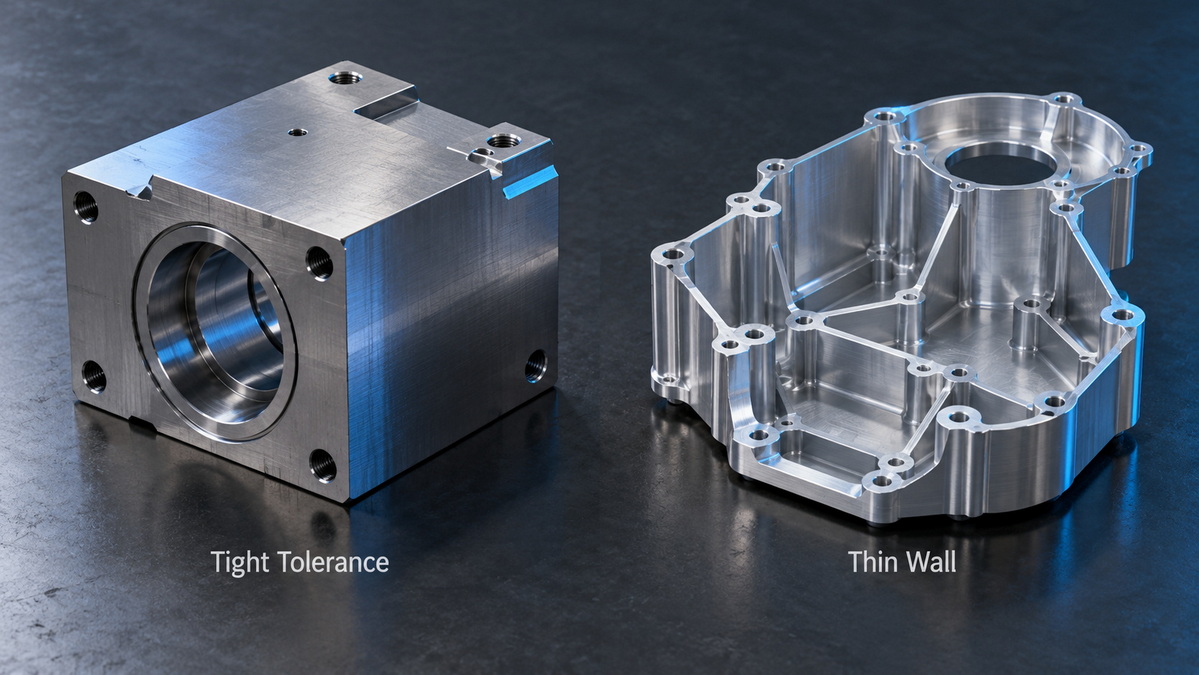
Tight tolerance machining is an accuracy requirement, not a particular component shape. It may apply to a bearing bore, locating pin, sealing surface, mold insert, or precision housing.
Thin-wall machining is a structural challenge. A wall becomes machining-sensitive when its geometry and support allow meaningful movement under process loads. There is no universally applicable wall thickness that separates "thin" from "safe." Wall height, unsupported span, material, and boundary conditions all matter.
Published thin-wall research identifies cutting forces, workholding, machining strategy, and residual stresses as important contributors to deformation. It also shows why dimensions measured while a component is clamped may not represent its released shape.
| Comparison factor | Tight tolerance machining | Thin-wall CNC parts |
|---|---|---|
| Primary requirement | Small permissible dimensional or geometric error | Stable machining of flexible geometry |
| Main design concern | Functional limits, datums, and tolerance allocation | Wall thickness, unsupported span, and support |
| Typical process sensitivity | Tool wear, thermal drift, setup repeatability | Cutting-force deflection, clamping distortion, stress redistribution |
| Inspection concern | Measurement uncertainty relative to tolerance | Measurement uncertainty plus inspection-induced deformation |
| Combined challenge | Accurate features on a stable component | Accurate features on a component whose shape can change |
The categories overlap. A thin enclosure with a precision bearing seat requires both approaches.
Wall thickness alone is an incomplete predictor of machinability.
A short wall supported by adjacent ribs may remain stable, while a taller wall of identical thickness may deflect substantially. Broad, thin floors can also bow even when the surrounding walls appear robust.
Thin-wall machining literature uses height-to-thickness ratios to help distinguish machining strategies. These ratios are planning guidance, not universal acceptance limits. Support conditions and material behavior still determine whether a particular design can meet its drawing requirements.
During design review, examine:
- Maximum unsupported wall height.
- Distance between ribs or supporting features.
- Thin floors beneath deep pockets.
- Open edges and interrupted walls.
- Flexible transitions around holes and slots.
Where function permits, reducing unsupported span may be more useful than increasing thickness everywhere.
Deep pockets introduce two interacting problems: flexible workpiece geometry and limited tool access.
A cutter that must reach far below the component surface may require extended tooling. Sandvik Coromant specifically identifies deep features, thin sections, and weak clamping as conditions requiring dedicated tooling and machining strategies.
From a design-review perspective, consider whether:
- A pocket can be shallower.
- An internal radius can accommodate a more robust cutter.
- A feature can be accessed from another direction.
- A narrow opening unnecessarily restricts tool diameter.
- A critical surface can be finished before surrounding material is removed.
The objective is not to eliminate complexity. It is to avoid geometric restrictions that add manufacturing risk without improving function.
Residual stress can exist in the starting material before machining begins. Removing material changes the balance of those stresses.
A large pocket machined predominantly from one side may therefore create distortion that becomes apparent after unclamping. Machining can also introduce additional stresses through mechanical and thermal loading.
Research on thin-walled components distinguishes initial residual stress from machining-induced residual stress. Their relative influence varies with material, geometry, and machining stage; neither should be treated as a universally dominant cause.
Design implications include:
- Review heavily one-sided pockets.
- Avoid unnecessary abrupt thickness transitions.
- Identify broad surfaces vulnerable to bowing.
- Discuss stock condition before finalizing the process.
- Allow the supplier to propose staged material removal.
A geometrically symmetric component is not automatically distortion-free, but symmetry can simplify process planning.
A datum defines how a feature is located or oriented for manufacturing and verification. Its practical value depends partly on whether the corresponding physical surface remains stable.
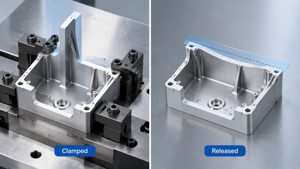
A flexible wall may be a poor locating surface if fixture pressure changes its shape. Similarly, a component can appear conforming while restrained and move outside its limits when released.
Thin-wall research reports significant deformation following the removal of clamping forces because the workpiece reaches a different stress and shape equilibrium.
For critical parts, identify:
1. Stable locating surfaces.
2. Suitable clamp-contact areas.
3. Features that require local support.
4. The required inspection condition.
5. Whether assembled restraint is part of the functional requirement.
Manufacturing and inspection should not rely on different, unstated interpretations of the same datum system.
Material selection changes more than cutting speed. It affects elastic response, thermal expansion, stock condition, and the suitability of stress-management treatments.
Temperature also changes measured dimensions. NIST explains that industrial dimensional measurements use 20°C as the standard reference temperature. Measurements at other temperatures require appropriate consideration of thermal expansion and associated uncertainty.
For tight tolerances, specify the material grade and condition rather than relying only on a broad description such as "aluminum" or "steel."
For thin-wall components, also discuss whether the proposed material and stock form are compatible with the intended geometry and manufacturing sequence.
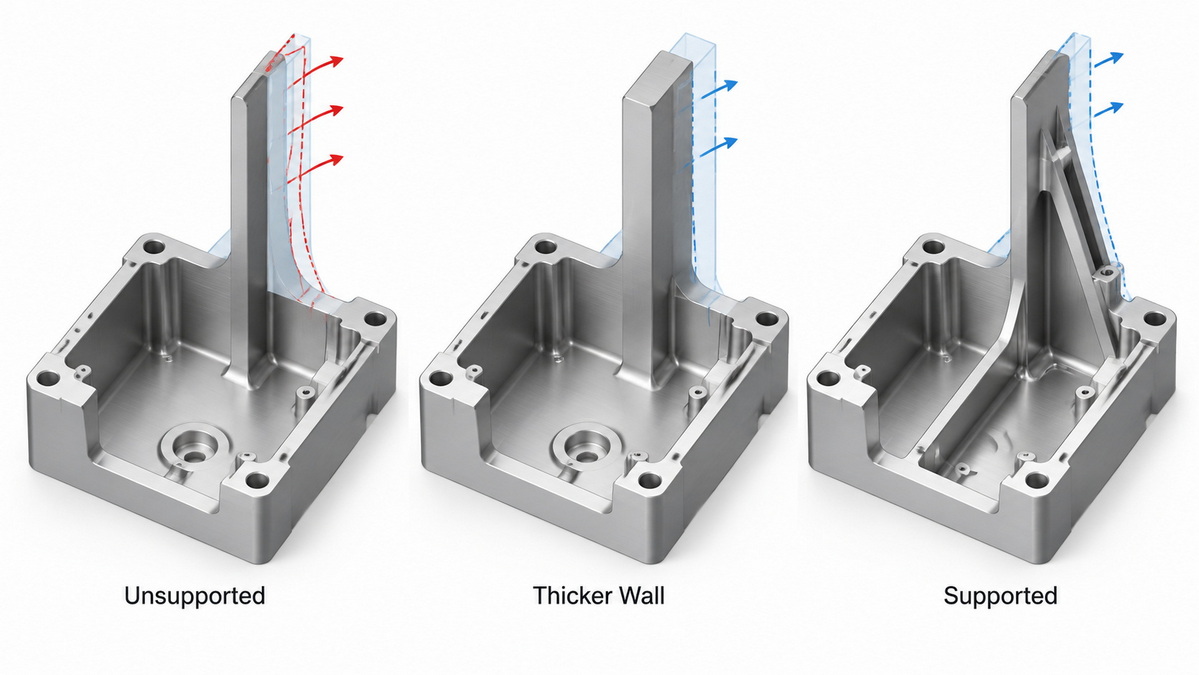
A drawing communicates the allowable result. It does not make the workpiece more rigid.
If a thin wall moves during cutting, the programmed tool position and the unloaded wall surface may differ. Thin-wall milling research describes elastic wall deflection and springback as mechanisms affecting final geometry.
Consequently, tighter tolerances may require more than an additional finishing pass. They may require different support, tool engagement, sequencing, or feature design.
A wall can have acceptable local thickness but still be bowed. A bore can meet its diameter requirement but be incorrectly located relative to a mating interface.
A useful drawing review separates:
- Size: thickness, diameter, width, or length.
- Form: flatness, straightness, or cylindricity.
- Orientation: perpendicularity or parallelism.
- Location: position relative to functional datums.
This distinction prevents a single dimensional tolerance from being expected to control every aspect of performance.
Apply demanding requirements to functional features. Avoid extending them automatically to noncritical surfaces.
Begin with the product's actual risk.
Does variation cause leakage, interference, bearing misalignment, uneven sealing, or assembly difficulty?
Translate that failure into specific drawing requirements. "Make everything precise" is less actionable than identifying the surfaces that control fit and function.
Mark thin walls, thin floors, deep pockets, and long unsupported spans.
Then identify potential supporting ribs, thicker locating regions, temporary material, or accessible fixture contacts. Keep the review focused on the features whose movement would affect acceptance.
Discuss how the component changes stiffness during machining.
Thin-wall literature recommends retaining unmachined material as local support and selecting strategies according to wall geometry. Depending on the component, alternate-side machining, staged finishing, or temporary ribs may help.
Do not prescribe a universal sequence without considering the actual geometry.
Reducing cutting load requires coordination between tool geometry, engagement, toolpath, and workpiece support.
Sandvik Coromant notes that thin-wall strategies should vary with wall height and thickness, and describes reduced engagement and step-support approaches for appropriate geometries.
"Take lighter cuts" is therefore a starting principle, not a complete process specification.
Agree on:
- Measurement datums.
- Supported, restrained, or free-state conditions.
- Temperature handling.
- Critical measurement locations.
- Appropriate instruments and probing strategy.
- Required inspection documentation.
Resolve these details before approving a production process.
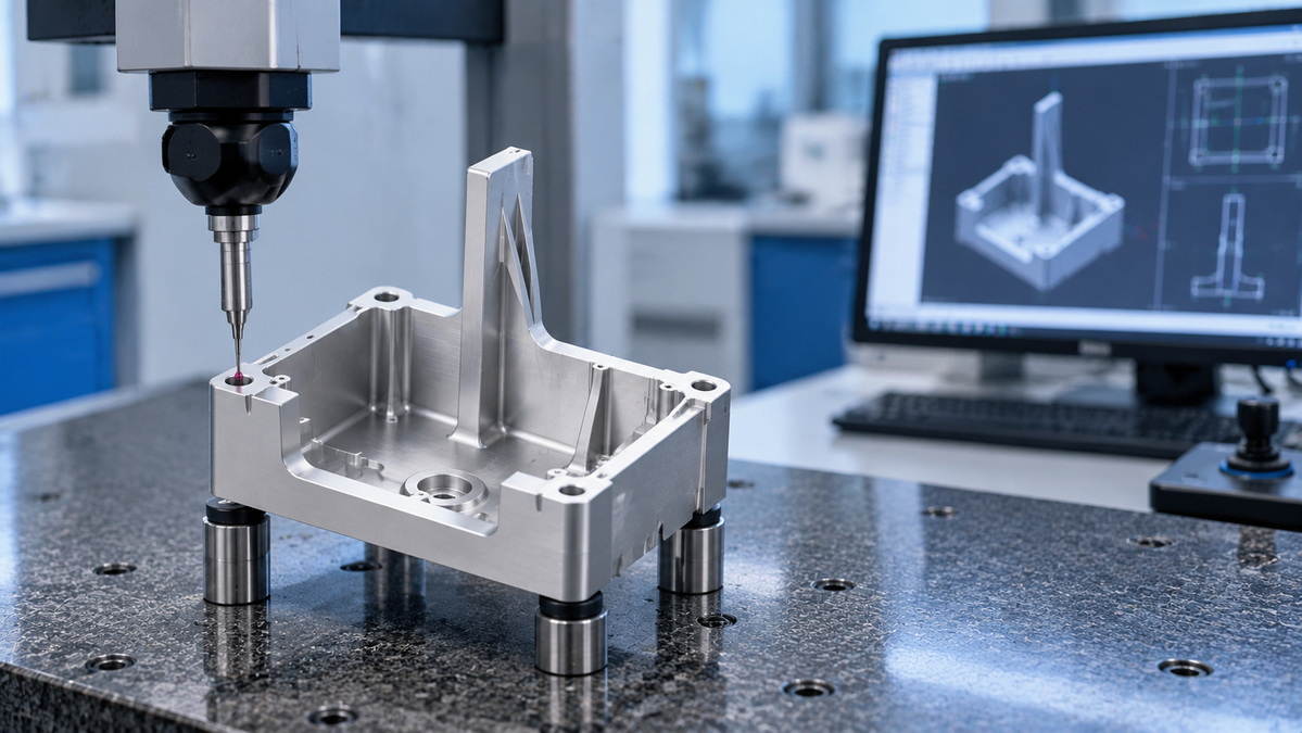
Its value is practical: it discourages teams from attributing every failed measurement to machine positioning.
NIST's work on nonstandard-temperature measurement similarly emphasizes that temperature and thermal-expansion uncertainty must be considered when assessing dimensional results.
Consider an illustrative thin aluminum housing with a machined sealing flange.
The flange measures acceptably while held in the fixture but bows after release. This hypothetical example is not a U-Need customer case.
The investigation should compare:
1. The restrained measurement.
2. The released measurement.
3. The thermally stabilized measurement.
The differences help distinguish fixture influence, stress release, and thermal effects. A repeatable clamped result alone does not establish a repeatable finished part.
A 2025 study on thin-wall milling reported substantial post-machining deformation for its 1 mm wall condition and found that wall thickness and cutting speed affected flatness and thickness deviation in aluminum alloy 7050-T7451.
The useful lesson is not that every 1 mm wall will fail.
It is that published results remain tied to their tested material, geometry, tooling, and process. Supplier capability should be evaluated against the proposed component—not inferred from a generic minimum-wall claim.
A useful request for quotation connects design intent with acceptance criteria.
Provide:
- A 3D model and revision-controlled drawing.
- Material grade and required condition.
- Critical dimensions and geometric controls.
- Functional datums and mating interfaces.
- Surface-finish and coating requirements.
- Prototype and production quantities.
- Inspection and documentation expectations.
- Areas where design changes are acceptable.
For thin-wall CNC parts, explicitly identify any required inspection restraint and any functional surfaces that must remain stable after unclamping.
Ask the supplier to explain its proposed support, machining sequence, and verification approach rather than requesting only a tolerance promise.
U-Need's stated services include custom precision parts machining, mold manufacturing, and sheet metal fabrication. That scope supports a discussion of whether a component should be machined, formed, or redesigned around another production route.
For a targeted review, send U-Need your model, drawing, material specification, production quantity, and critical acceptance requirements.
Request a DFM assessment focused on unsupported walls, tool access, datum stability, distortion risk, and final inspection conditions. Confirm project-specific capability before treating any demanding tolerance as a production commitment.
Tight tolerance machining concerns permissible error. Thin-wall machining concerns flexible geometry. A component can require either approach or both.
No universal threshold applies across all geometries and materials. Wall height, unsupported span, support conditions, and machining strategy influence practical feasibility.
Clamping can restrain elastic movement. Releasing the fixture allows a new equilibrium influenced by residual stresses and the component's remaining structure.
Machine accuracy alone cannot eliminate workpiece deflection or stress-related distortion. Thin-wall machining also requires suitable support, tooling, and process planning.
Tolerance requirements should reflect function. Identify the features controlling assembly and performance, then discuss achievable capability and inspection requirements with the supplier.
Prioritize functional datums, the required restraint condition, thermal considerations, and a measurement method suitable for the component's flexibility and tolerance. NIST guidance establishes the importance of reference temperature and thermal uncertainty.
1. NIST. [Selected Publications on Dimensional Metrology—20-Degree Reference Temperature]. Basis for the dimensional reference-temperature discussion.
2. NIST. [Handbook 143, Section 6.1]. Guidance on thermal corrections and measurement uncertainty.
3. NIST. [Uncertainties in Dimensional Measurements Made at Nonstandard Temperatures]. Basis for the temperature-related uncertainty discussion.
4. Sandvik Coromant. [What Is Successful Milling?]. Tool-access, rigidity, and clamping considerations.
5. Sandvik Coromant. [Machining Aluminum for Lighter Components and a Recyclable Future]. Thin-wall engagement and support strategies.
6. Peer-reviewed research, 2020. [Techniques for Thin-Walled Element Milling with Respect to Deformation Minimization]. Wall geometry, machining sequence, clamping, and deformation mechanisms.
7. Peer-reviewed research, 2025. [Thin Wall Milling at a Maximized Axial Depth of Cut]. Study-specific findings on wall thickness, cutting speed, and post-machining deformation.
8. The International Journal of Advanced Manufacturing Technology, 2026. [Analysis of Machining Strategies in Terms of Residual Stress and Post-Machining Deformation]. Initial and machining-induced residual-stress considerations.


