Views: 288 Author: U-Need Publish Time: 2026-08-21 Origin: Site
Content Menu
● Why CNC Collision Prevention Matters in Precision Manufacturing
● The Six Core Methods to Prevent CNC Machine Collisions
>> 1. Verify Toolpaths With CNC Simulation Software
>> 2. Use the Machining Center's Graphic Verification Function
>> 3. Perform a Controlled Dry Run Before Cutting
>> 4. Use Axis Lock and Machine Lock Functions Correctly
>> 5. Set Work Coordinates and Tool Offsets With Discipline
>> 6. Improve CNC Programming Habits and Safety Logic
● A Better Workflow for First-Part Verification
● Practical Expert Checklist Before Cycle Start
● How U-Need Supports Safer, More Consistent Production
>> 1. What is the most effective way to prevent a CNC collision?
>> 2. Can CNC simulation completely prevent machine crashes?
>> 3. Why are tool length offsets important in CNC milling?
>> 4. Should a new CNC program always be dry-run?
>> 5. What should an operator watch during a dry run?
>> 6. Why should the tool retract before moving in X and Y?
A CNC machining center collision can damage spindles, toolholders, fixtures, cutting tools, and valuable customer parts within seconds. For buyers who rely on precision manufacturing in China, preventing crashes is not only a shop-floor safety task—it is essential for protecting dimensional consistency, lead time, and repeatable production quality.
At U-Need, our machining teams treat collision prevention as a controlled verification process rather than a last-minute operator check. The strongest approach combines CAM simulation, machine-side program verification, dry runs, accurate coordinate settings, validated tool offsets, and disciplined CNC programming. Together, these measures help custom precision parts machining projects run more safely from prototype through repeat production.

A CNC crash is unintended contact between a cutting tool, toolholder, spindle, workpiece, fixture, vise, chuck, or another machine component. The immediate consequence may be a broken tool or scrapped part. The larger impact can include spindle damage, fixture misalignment, rework, production delays, and inconsistent quality across future batches.
For global brands, distributors, and manufacturers sourcing precision parts, a reliable supplier should have practical controls in place before machining begins. This matters especially when a project includes:
- Tight-tolerance CNC milling or turning
- Deep cavities, thin walls, or complex contours
- Multi-axis machining operations
- Custom fixtures and workholding
- Multiple tool changes in one program
- Expensive materials or limited-quantity prototype parts
- Mold components for injection molds, stamping dies, or cold-forging dies
A collision-free first-part process supports more stable cycle times and reduces avoidable interruptions. It also helps protect the machine accuracy that customers depend on for long-term production programs.
Computer simulation should be the first technical checkpoint after a CNC program is generated. The programmer imports the NC code into simulation software and reviews tool motion before the program reaches the machine.
A useful simulation should show more than the cutter moving around a digital workpiece. It should account for the machine configuration, toolholder, tool geometry, stock material, fixture, clamps, and toolpath sequence. Siemens notes that collision detection can use look-ahead calculations to identify potential collisions in advance and actively avoid them in applicable control environments.
Simulation is particularly valuable for detecting:
- Rapid moves that pass too close to clamps or vises
- Toolholder interference in deep pockets
- Incorrect approach or retract movements
- Unexpected axis movement after a tool change
- Overtravel near machine travel limits
- Incorrect tool length or diameter data in the virtual setup
- Risky five-axis indexing or rotary-axis positions
However, simulation does not remove the need for machine-side verification. A digital model is only as accurate as the tool, fixture, stock, and offset information entered into it. A simulation may be clean while the real setup still contains a wrong offset or incorrectly loaded tool.
Many modern CNC machining centers offer a built-in graphical display function. Once the program is loaded, the operator can view the planned tool motion directly at the control.
This is a fast and practical secondary check. It allows the team to review whether the programmed path logically matches the setup and machining plan before the spindle begins cutting.
The machine display is useful for confirming:
- The selected work coordinate system
- The direction of X, Y, and Z movement
- Tool-change locations
- Major rapid-traverse moves
- The sequence of roughing, finishing, drilling, and contouring operations
- Possible interference between the tool, part, and fixture
Built-in graphics are not a substitute for full machine-aware simulation, but they are an effective line of defense at the machine. They help the operator confirm that the loaded code matches the intended production setup.
A dry run executes the CNC program on the actual machine with cutting disabled or with the tool held at a safe distance from the workpiece. It is one of the most important checks for a new program, revised setup, or unfamiliar fixture arrangement.
A dry run can reveal real-world issues that software cannot always capture, such as an incorrect tool in a magazine pocket, a clamp positioned differently from the setup drawing, or a work offset entered into the wrong register. One practical verification guide recommends starting new programs slowly, reducing rapid and feed overrides to roughly 5–10%, and using single-block mode for early program lines and high-risk movements.
A safe first-run sequence is:
1. Confirm the correct program revision is loaded.
2. Check that the actual tools match the programmed tool numbers.
3. Confirm toolholders, clamps, vises, and workpieces are secure.
4. Move the spindle to a known safe height above the highest fixture point.
5. Enable dry-run or machine-lock functions according to the control's instructions.
6. Reduce rapid and feed overrides before starting.
7. Use single-block mode for initial rapid moves, tool changes, and clearance-critical sections.
8. Watch the full moving assembly—not only the cutting edge.
9. Stop immediately if axis direction, clearance, or tool selection appears wrong.
10. Return the machine to its reference position after verification when required by the machine procedure.
Never assume that a successful simulation means the first physical run can start at full speed. Dry running verifies the real machine, real fixture, real tool assembly, and real operator setup.
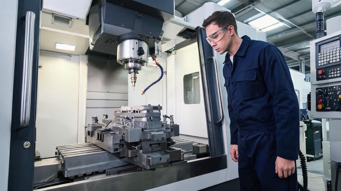
Many machining centers provide machine-lock, axis-lock, or related control functions. Used correctly, these features let an operator evaluate programmed movements without allowing all axes or the spindle to perform a normal cutting cycle.
For example, locking the Z axis while reviewing a program can help the operator evaluate whether a commanded vertical movement would create a collision risk. The displayed coordinate values can then be checked against the fixture height, workpiece surface, planned clearance plane, and tool geometry.
This method is especially useful when verifying:
- First tool approach after a tool change
- Deep-pocket machining operations
- Fixture-rich setups with clamps close to the cutting area
- Programs transferred from a different machine
- Revised code after engineering changes
Axis lock is a verification aid, not a replacement for the full process. Operators should understand exactly how their individual CNC control behaves in locked, dry-run, and single-block modes. Incorrect use of dry-run or lock settings can itself create risk, including unexpected rapid movement if the machine mode is misunderstood.
Correct coordinate systems and tool offsets are fundamental to safe CNC machining. A toolpath can be perfectly programmed and still crash if the work offset, tool length, or tool radius value is wrong.
The machine coordinate system is fixed by the machine's reference position. The work coordinate system is a user-defined reference that places program zero relative to the actual workpiece. Beckhoff's CNC documentation explains that, after reference searching, the control is located at machine zero or within the machine coordinate system, while tool offsets are managed separately through parameter data.
For milling operations, the critical checks usually include:
| Verification item | What to confirm | Collision risk if wrong |
|---|---|---|
| Work offset | The selected G54/G55/G56 location matches the setup drawing and program | Tool approaches the part or fixture from an unexpected location |
| Z zero | The programmed Z reference matches the actual part surface or datum | Tool cuts too deep or descends into the part |
| Tool number | The tool called by the program matches the tool loaded in the magazine | Wrong diameter, length, or toolholder geometry |
| Length offset | The correct length value is stored in the correct offset register | Tool stops too high, cuts too deep, or hits the fixture |
| Radius/diameter offset | Compensation value matches the actual cutter | Excess material, undersize features, or side collision |
| Tool stick-out | Actual projection from the holder matches the planned setup | Holder may strike walls, clamps, or cavity features |
Tool length compensation is particularly important because it accounts for differences in tool length within the magazine. A guide to G43 compensation warns that incorrect H-offset selection, applying compensation at the wrong time, or cancelling it improperly can create crash conditions.
A robust setup process includes independent confirmation of the work offset and tool length data. Tool lengths should be checked after tool changes, regrinding, insert replacement, or any adjustment that changes the effective cutting position.
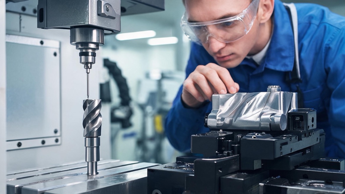
Strong programming habits reduce risk before an operator ever presses Cycle Start. Safe code is not only about generating the desired geometry. It must also define how the machine enters, exits, retracts, changes tools, and moves between operations.
A common mistake occurs when a tool finishes machining inside a pocket or cavity and then travels laterally before retracting to a safe Z height. Even if the final cutting point is correct, a rapid X/Y move at a low Z level may drive the tool, holder, or spindle assembly into the workpiece wall or fixture.
Consider this simplified sequence:
N40 G00 Z100.
N50 G00 X0 Y0
The code first retracts the tool to a designated safe height, then moves horizontally to the programmed X/Y position. This is generally safer than commanding a lateral rapid move while the cutter remains near the workpiece.
The exact safety height must be based on the real setup. It needs to clear the highest workholding component, the workpiece, and any expected fixture variation. A practical collision-prevention guide recommends explicit safe Z heights for rapid movement and tool changes, often 10–25 mm above the highest fixture component when the setup allows it.
The strongest approach is not choosing between simulation and dry running. It is using each method for what it does best.
| Stage | Main purpose | Typical issue detected |
|---|---|---|
| CAM review | Confirm machining strategy and toolpath logic | Incorrect toolpath, missing retract, poor sequence |
| Full simulation | Check digital machine, fixtures, stock, tool, and holder clearance | Virtual collisions and inaccessible geometry |
| Setup verification | Confirm actual tooling, fixture, workpiece, and program revision | Wrong tool, fixture mismatch, wrong setup condition |
| Control graphics | Review code behavior at the machine | Incorrect coordinate selection or unexpected path |
| Dry run | Validate physical motion at reduced speed | Offset error, wrong tool, unsafe real clearance |
| First-part machining | Confirm cutting conditions and final dimensions | Material, tolerance, or process variation |
This layered method is more reliable because each stage catches a different class of error. Simulation is strong at finding programmed geometry conflicts. Dry running is strong at finding physical setup and execution errors. Neither should be treated as optional on complex or high-value parts. A comparison of simulation and dry-run methods similarly recommends simulation first, followed by a single-block dry run on the first part, then full-speed production once verification is complete.
Before releasing a new precision machining program, a qualified setup team should confirm the following:
- The latest approved program revision is loaded.
- The drawing datum and programmed datum are consistent.
- The correct work offset is active.
- The part is clamped securely and matches the setup plan.
- Clamp height and fixture envelope have been checked.
- Every programmed tool number matches the actual magazine pocket.
- Tool lengths, diameters, and offset registers have been verified.
- Toolholders have sufficient clearance in pockets, walls, and deep cavities.
- Safe Z positions clear the highest clamp and fixture feature.
- The first rapid moves and tool changes have been reviewed.
- Dry-run, machine-lock, and single-block modes are understood before use.
- Rapid and feed overrides are reduced for the initial run.
- The operator can reach the emergency stop without obstruction.
This checklist is simple, but its value comes from consistent use. Precision manufacturing depends on repeatable systems, not memory alone.
U-Need provides end-to-end manufacturing support for global brands, distributors, and industrial manufacturers. Our capabilities include custom precision parts machining, injection mold manufacturing, stamping dies, cold-forging dies, laser cutting, bending, stamping, and other sheet metal fabrication processes.
For a complex precision part, safety and quality begin long before production. The manufacturing team should review drawings, tolerances, materials, tool access, workholding, inspection requirements, and the most suitable machining sequence. That engineering-led preparation makes collision prevention part of process control—not merely an operator's final check.
Whether you need prototype machining, low-volume production, repeat parts, mold components, or integrated metal fabrication, share your drawing, material requirement, annual volume, tolerance expectations, and inspection needs with U-Need. Our team can assess manufacturability and develop a production approach that balances accuracy, safety, lead time, and cost.
The most effective method is a layered workflow: simulate the NC program, verify the actual setup, review the control graphics, perform a reduced-speed dry run, and use single-block mode for high-risk movements. Each check catches different errors.
No. Simulation can detect many toolpath and digital setup issues, but it depends on accurate input data. It may not detect a wrong physical tool, an incorrectly clamped workpiece, an offset entered in the wrong register, or a changed fixture condition on the machine.
Tool length offsets tell the machine where the cutting tip is relative to a reference point. If the value is wrong, the tool may cut too deep, stop too high, or collide with the workpiece or fixture.
For new, revised, complex, or high-value work, a dry run is strongly recommended. It provides a real-machine confirmation of clearance, tool selection, coordinate setup, and motion direction before cutting begins.
Watch the cutting tool, toolholder, spindle, vise, clamps, fixture, workpiece, and each axis movement. Pay close attention to rapid moves, initial Z-axis descent, tool changes, pocket entry, retracts, and any movement near clamps.
Retracting to a safe Z level before a lateral rapid move helps prevent the tool or holder from striking part walls, clamps, or fixtures. The safe height must be defined based on the highest element in the real setup.
1. Siemens. "SINUMERIK Programming Guide: Tool Offset and Collision Detection." [Read the document].
2. Beckhoff. "Coordinate Systems." [Read the documentation].
3. Eureka. "G43 Tool Length Compensation." [Read the guide].
4. Eureka. "CNC Simulation vs Dry Run." [Read the comparison].
5. East CNC. "Collision Risk When Debugging a CNC Program: A Checklist." [Read the checklist].
6. Bangid. "Preventing CNC Machine Crashes." [Read the article].
7. Xinmei Intelligent. "CNC Coordinate Systems: Master Offsets." [Read the guide].


