Views: 209 Author: U-Need Publish Time: 2026-10-22 Origin: Site
Content Menu
>> Where Plain Milling Fits Best
>> Where Face Milling Fits Best
● Plain Milling vs. Face Milling: Key Differences
● Surface Finish and Flatness: What Actually Controls Quality?
>> Surface Roughness Is Not Flatness
● Productivity and Cost: Compare the Entire Route
>> When Plain Milling Can Be Economical
>> When Face Milling Can Reduce Total Cost
● Material and Geometry: Match the Process to the Workpiece
>> Thin Plates and Delicate Features
● A Practical Workflow for Choosing the Milling Process
>> Step 1: Define the Functional Surface
>> Step 2: Check Access and Support
>> Step 3: Compare Complete Machining Routes
>> Step 4: Validate Cutting Conditions
>> Step 5: Confirm First-Article Results
● Worked Example: Why Removal Rate Is Only One Metric
● Application Scenarios: Mold Plates and Precision Parts
>> Mold Plate with Holes and Pockets
>> Repeated Rectangular Machine Components
● What to Include in a Precision Machining Inquiry
● Discuss Your Manufacturing Requirements with U-Need
>> 1. What is the main difference between plain milling and face milling?
>> 2. Is plain milling the same as slab milling?
>> 3. Does face milling always produce a better surface finish?
>> 4. Which process is better for removing large amounts of material?
>> 5. Can face milling produce pockets?
>> 6. Can milling meet every precision flatness requirement?
Plain milling vs. face milling is a practical decision when manufacturing flat surfaces for precision parts, mold plates, and industrial components. Both processes remove material with rotating cutters, but their tool orientation, cutting forces, and setup requirements differ.
The fundamental difference is orientation: in plain milling, the cutter axis runs parallel to the machined surface; in face milling, it runs perpendicular to that surface.
For buyers and engineers, however, knowing this distinction is only the beginning. The better process must also suit the material, part geometry, inspection requirements, and production quantity.
From a manufacturing-planning perspective, I would start with the finished part's function—not a preferred cutter. This guide explains how to make that decision and prepare a more useful machining inquiry.
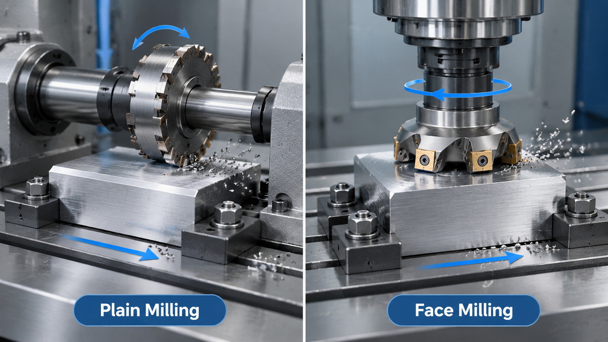
Plain milling, commonly called slab milling, creates flat surfaces using cutting edges around the circumference of a cylindrical cutter. The cutter axis remains parallel to the surface being generated.
A typical setup uses a horizontal spindle and an arbor-mounted cutter. The workpiece feeds beneath the rotating tool, which removes material across the selected cutting width.
Plain milling deserves consideration for:
- Long, accessible flat surfaces.
- Repeated machining of similar rectangular components.
- Stock removal on rigid workpieces.
- Production suited to an existing horizontal milling setup.
Its attraction is not simply cutting speed. A well-supported cutter and repeatable fixture can make a straightforward surface-machining operation productive.
However, cutter width, arbor stiffness, available power, and workholding all limit performance. A wide cutter does not automatically deliver a lower cost per part.
Face milling produces a flat surface perpendicular to the cutter's rotational axis. Cutting edges around the tool's periphery remove material, while the face and corner geometry help generate the finished surface.
Face mills commonly use replaceable inserts, although other tool designs can perform facing operations.
The process is frequently associated with vertical machining centers, but spindle orientation alone does not define it. The relationship between the tool axis and the machined surface does.
Typical applications include:
- Establishing reference faces on machined blocks.
- Surfacing mold plates and fixture bases.
- Preparing mounting interfaces.
- Facing parts before machining holes, pockets, or shoulders.
Face milling integrates readily into machining routes containing several different features. That integration can matter more than the cutting time of the facing operation alone.
| Comparison factor | Plain milling | Face milling |
|---|---|---|
| Cutter axis | Parallel to the machined surface | Perpendicular to the machined surface |
| Typical cutter | Cylindrical slab cutter | Face mill, often with indexable inserts |
| Main cutting region | Cutter circumference | Peripheral, corner, and face cutting regions |
| Typical setup | Horizontal spindle with arbor support | Vertical or suitably oriented spindle |
| Strong application fit | Accessible flat surfaces and repeatable stock removal | Reference faces and integrated machining routes |
| Main stability concerns | Arbor deflection, cutter engagement, workholding | Tool overhang, insert runout, force direction |
| Finishing considerations | Cutter condition, alignment, feed, rigidity | Insert geometry, runout, tool path, rigidity |
| Cost advantage | Depends on the complete production setup | Depends on the complete production setup |
Neither process guarantees better accuracy, faster machining, or lower cost. Those outcomes depend on the actual machine, tool, workpiece, and inspection plan.
A frequent oversimplification is that plain milling removes material while face milling delivers precision. Both processes can rough and finish surfaces when properly configured.
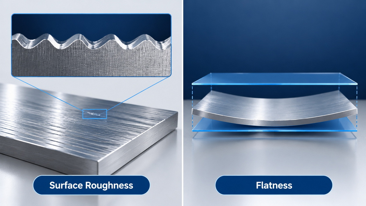
Surface roughness describes relatively small surface irregularities. Flatness describes the overall form of a surface.
A plate can look smooth yet fail its flatness requirement. Conversely, a sufficiently flat surface may still have visible machining marks.
When reviewing a drawing, separate:
- Surface roughness requirements.
- Flatness tolerances.
- Parallelism to another surface.
- Thickness tolerances.
- Conditions during inspection.
These requirements affect process planning differently.
Face milling can leave steps between passes if alignment, tool condition, or cutting-edge runout is unsuitable.
Plain milling can suffer from arbor deflection, cutter wear, or unstable engagement.
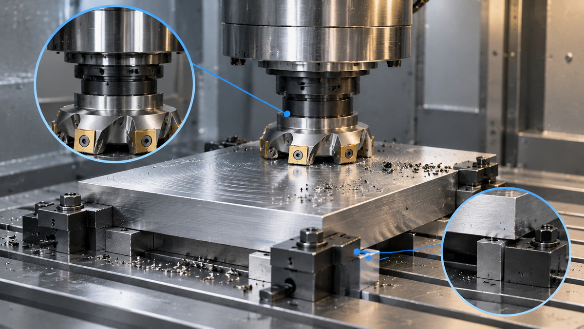
Either process can produce a part that changes shape after unclamping. This is especially important for thin plates, where clamping pressure may temporarily flatten the workpiece.
My preferred purchasing question is therefore not "Which process is more accurate?" It is "How will the supplier control and verify the required surface after machining?"
A productive cutting operation is not necessarily an economical manufacturing route.
A supplier may remove stock quickly but lose that advantage through additional setups, handling, inspection, or rework.
Plain milling can be attractive when:
1. The surface is easy to access.
2. The workpiece can be supported rigidly.
3. The cutter suits the required machining width.
4. Production volume justifies dedicated workholding.
5. The available machine supports the required cutting load.
Repeated parts can benefit from a stable, established setup.
Face milling may be the better route when the same setup also supports drilling, pocketing, and shoulder machining.
For example, a component requiring a flat reference face and a hole pattern may be processed efficiently on one machining center. Avoiding another setup can reduce handling and simplify datum control.
A useful quotation comparison should include setup time, cycle time, tooling consumption, inspection, and expected yield—not just the hourly machine rate.
Material selection influences cutting geometry, cutting conditions, and chip evacuation. Geometry determines how well the workpiece resists those cutting forces.
For aluminum plates and housings, consider chip evacuation, cutting-edge sharpness, and resistance to material buildup.
Thin sections require particular attention. An aggressive cut that performs well on solid stock may distort a lightweight housing.
Tool grade, edge preparation, engagement, and machine rigidity become important when machining steels.
Stainless steel requires controlled cutting conditions; prolonged rubbing with an unsuitable edge can undermine the process. Cutting recommendations should come from the tool manufacturer for the actual material and tool combination.
For thin floors or unsupported walls, force direction matters as much as force magnitude.
Face-mill entering angle changes the distribution of axial and radial forces. A geometry that helps one setup may destabilize another.
The practical lesson is to choose the tool and fixture together rather than treating workholding as an afterthought.
Identify what the surface must do.
Does it locate another component, support a seal, establish a machining datum, or simply provide clearance? Apply demanding requirements where function justifies them.
Review cutter clearance, travel limits, clamping positions, and unsupported spans.
A theoretically efficient process may become impractical if the cutter cannot reach the surface without compromising workholding.
Evaluate at least two realistic sequences.
One route might use plain milling for stock preparation. Another might use face milling followed by drilling and pocketing in the same setup.
Compare the finished component, not isolated tool movements.
Select starting parameters from the tooling supplier's recommendations. Adjust for material condition, engagement, overhang, and machine limits.
Avoid copying cutting data from a different tool or alloy without checking its applicability.
Inspect the first part before releasing the batch. Check dimensions, surface condition, burrs, and distortion after unclamping.
For demanding work, retain the inspection results and approved process settings.
Material removal rate helps compare cutting conditions, but it does not establish total manufacturing cost.
These are illustrative values, not recommended cutting parameters.
Even if two processes achieve this same rate, their total costs may differ because of approach moves, tool changes, setup time, and inspection.
For procurement decisions, calculate cost per accepted component rather than ranking suppliers by removal rate alone.
The following are planning examples, not documented customer projects.
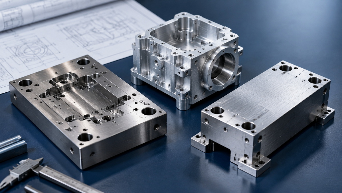
A mold plate needs a reference face, mounting holes, and machined pockets.
Face milling may integrate well into the machining-center sequence. However, if the plate requires substantial stock preparation and a suitable horizontal setup is available, plain milling may deserve evaluation.
Subsequent heat treatment or unusually demanding surface requirements may also change the route.
A batch of rigid components requires the same accessible flat surface.
Plain milling may be competitive when the cutter and fixture match the workpiece. Face milling remains a valid alternative, particularly if additional features can share its setup.
The decision should follow route costing and trial results—not a universal rule.
A useful inquiry gives the manufacturer enough information to assess both feasibility and process risk.
Include:
- A dimensioned drawing and available 3D model.
- Material grade and supply condition.
- Order quantity and expected repeat demand.
- Critical datums and tolerances.
- Surface roughness and flatness requirements.
- Heat treatment or coating requirements.
- Inspection and documentation needs.
- Delivery requirements.
Specify functional outcomes rather than insisting on a machining method without a clear reason.
This leaves room for the supplier to propose a more economical route while remaining accountable to the drawing.
U-Need supports global brands, distributors, and manufacturers with custom precision parts machining, mold manufacturing, and sheet metal fabrication in China.
Its stated service scope includes injection molds, stamping dies, cold-forging dies, laser cutting, bending, and stamping.
Send U-Need your drawing, material specification, quantity, and critical surface requirements. Ask for a proposed manufacturing route covering workholding, finishing, and inspection—not simply a unit price.
That discussion creates a stronger basis for deciding whether plain milling, face milling, or a combined process best suits your component.
Plain milling places the cutter axis parallel to the machined surface. Face milling places it perpendicular to that surface. This changes cutter engagement and setup requirements.
In common manufacturing usage, yes. Slab milling describes flat-surface machining with a cylindrical cutter's peripheral teeth. Peripheral milling is a broader category that also includes other operations.
No. Face milling offers useful finishing options, but surface quality still depends on cutting-edge geometry, runout, cutting conditions, machine alignment, and workpiece stability.
Either may be suitable. Compare available power, cutter engagement, tooling, rigidity, and chip evacuation. Plain milling should not automatically be considered faster than a properly selected face-milling operation.
Face milling primarily creates exposed flat surfaces. Pockets typically require suitable end mills or other cutters with appropriate access and cutting capability. A facing operation alone does not establish pocket-machining capability.
No. Suitability depends on the tolerance, material, geometry, and inspection conditions. Some components require additional finishing, such as grinding or lapping, after milling.
1. [Xometry — "Plain Milling: Process, Uses, Advantages, and Disadvantages."] Supports plain-milling terminology, cutter orientation, operating principles, and applications. Its broad performance comparisons should be evaluated against actual production conditions. [xometry]
2. [ScienceDirect Topics — "Face Milling."] Supports the distinction between face and peripheral milling and explains the cutting regions involved. [sciencedirect]
3. [Sandvik Coromant — "Face Milling."] Supports face-milling tool selection, entering-angle considerations, and roughing and finishing applications. [sandvik.coromant]
4. [Sandvik Coromant — "Milling Formulas and Definitions."] Provides the basis for feed and removal-rate terminology. The numerical example above uses hypothetical inputs, not supplier performance data. [sandvik.coromant]
5. [Sandvik Coromant — "How to Reduce Vibration in Milling."] Supports the discussion of workholding, tool overhang, entering angles, and axial versus radial cutting forces. [sandvik.coromant]
6. [Sandvik Coromant — "Shoulder Milling."] Supports feature-specific tool selection and machining considerations for thin walls and unstable components. [sandvik.coromant]
7. [TOPS — "Plain Milling: A Versatile Machining Process."] Original topic supplied for editorial comparison. Technical definitions were cross-checked against the references above rather than adopting its classification of face milling as a type of plain milling. [topsbest-precision]


