Views: 221 Author: U-Need Publish Time: 2026-10-20 Origin: Site
Content Menu
● How Does a CNC Machining Center Work?
● Main Components of a Machining Center
● Types of Machining Centers: Vertical, Horizontal, and Five-Axis
>> Vertical Machining Center: Accessible and Versatile
>> Horizontal Machining Center: Multi-Sided Production
>> Five-Axis Machining Center: Greater Tool Access
● 3+2 Machining vs. Simultaneous Five-Axis Machining
● What Operations Can a Machining Center Perform?
● Machining Center vs. CNC Mill vs. Turning Center
● How to Choose the Right Machining Process for Your Part
>> Start with Geometry and Tool Access
>> Match the Process to Material and Quantity
>> Compare Complete Production Routes
● Precision Is a Process, Not Just a Machine Specification
>> Establish Consistent Datums
>> Use Probing to Control Variation
>> Verify the Finished Component
● Practical Example: Planning a Multi-Sided Aluminum Housing
● What Determines CNC Machined Part Cost?
● Working with U-Need on Precision Manufacturing Projects
● Start Your Precision Manufacturing Project
>> Is a machining center the same as a CNC machine?
>> Does every machining center have a pallet changer?
>> Can a machining center manufacture metal and plastic parts?
>> Is five-axis machining always more accurate?
>> What should I send for a machining quotation?
>> Can machining replace every other manufacturing process?
A machining center is a computer-controlled machine tool that performs operations such as milling, drilling, boring, reaming, and tapping using an automatic tool changer. For buyers sourcing precision components, understanding what a machining center does helps connect part geometry, production requirements, and supplier capabilities.
However, an advanced machine alone does not guarantee a successful component. Tooling, workholding, programming, material behavior, and inspection all influence the outcome.
This guide explains how CNC machining centers work, compares their main configurations, and provides a practical framework for evaluating precision manufacturing projects.
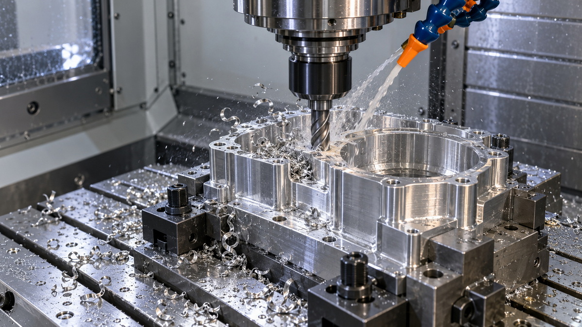
A machining center removes material from a workpiece with rotating cutting tools. Its computer numerical control system coordinates tool movement, spindle speed, feed rate, and supporting functions according to a programmed manufacturing sequence.
A typical workflow includes:
1. Reviewing the drawing, material, tolerances, and production quantity.
2. Developing toolpaths using computer-aided manufacturing software.
3. Securing the workpiece and establishing reference positions.
4. Loading tools and verifying their dimensions.
5. Executing the program and changing tools automatically.
6. Inspecting the component against its specified requirements.
The automatic tool changer allows different operations to run without an operator manually replacing every cutter. For example, one program might face a surface, mill a pocket, drill mounting holes, and tap threads.
Multiple operations can therefore share the same setup. However, inaccessible surfaces or restrictive clamping arrangements may still require repositioning.
Understanding the main components helps buyers ask more useful questions than simply requesting a machine model.
| Component | Function | Why it matters |
|---|---|---|
| Spindle | Rotates the cutting tool | Influences cutting capability and tool suitability |
| Linear axes | Position the tool or workpiece | Determine travel and access to features |
| Rotary axes | Change workpiece or tool orientation | Enable angled and multi-sided machining |
| Tool magazine and changer | Store and exchange tools | Support sequences involving multiple operations |
| Workholding system | Locates and secures the workpiece | Controls stability and repeatable positioning |
| CNC controller | Executes programmed instructions | Coordinates movement and machining functions |
| Coolant and chip system | Manages cutting fluid and removed material | Supports reliable cutting and chip evacuation |
| Probing system, when fitted | Measures tools or workpiece features | Supports setup verification and process control |
Automatic pallet changers, probing systems, and advanced tool-monitoring functions are configuration-dependent. They should not be assumed to exist on every machining center.
For axis terminology, the Z-axis follows the principal spindle axis rather than always pointing vertically. A, B, and C designate rotation around X, Y, and Z respectively.
A vertical machining center, or VMC, has a vertically oriented spindle. This arrangement provides straightforward access to the upper surface of the workpiece.
VMCs are commonly considered for plates, brackets, housings, mold components, and general milling work. Their suitability depends on part dimensions, cutting loads, tool access, and production requirements.
One practical concern is chip accumulation in pockets. Coolant delivery and chip removal deserve attention when machining deep cavities or running extended cycles.
A horizontal machining center, or HMC, uses a horizontally oriented spindle. Its configuration can help chips fall away from the cutting area.
Horizontal machines often use rotary tables and pallet systems to support multi-sided machining and production automation. They can be particularly useful when repeated loading, chip management, and access to several faces influence throughput.
Nevertheless, "horizontal" does not automatically mean better. The additional equipment and setup requirements must make economic sense for the work.
Five-axis machining adds two rotary axes to three linear axes. Different machines achieve this through rotating tables, tilting heads, or combined arrangements.
The main advantage is access: the tool can approach features from different directions, sometimes reducing the number of fixtures and setups.
This matters for angled holes, complex contours, and surfaces that are difficult to reach with a fixed tool orientation. It does not mean every component needs simultaneous five-axis cutting.
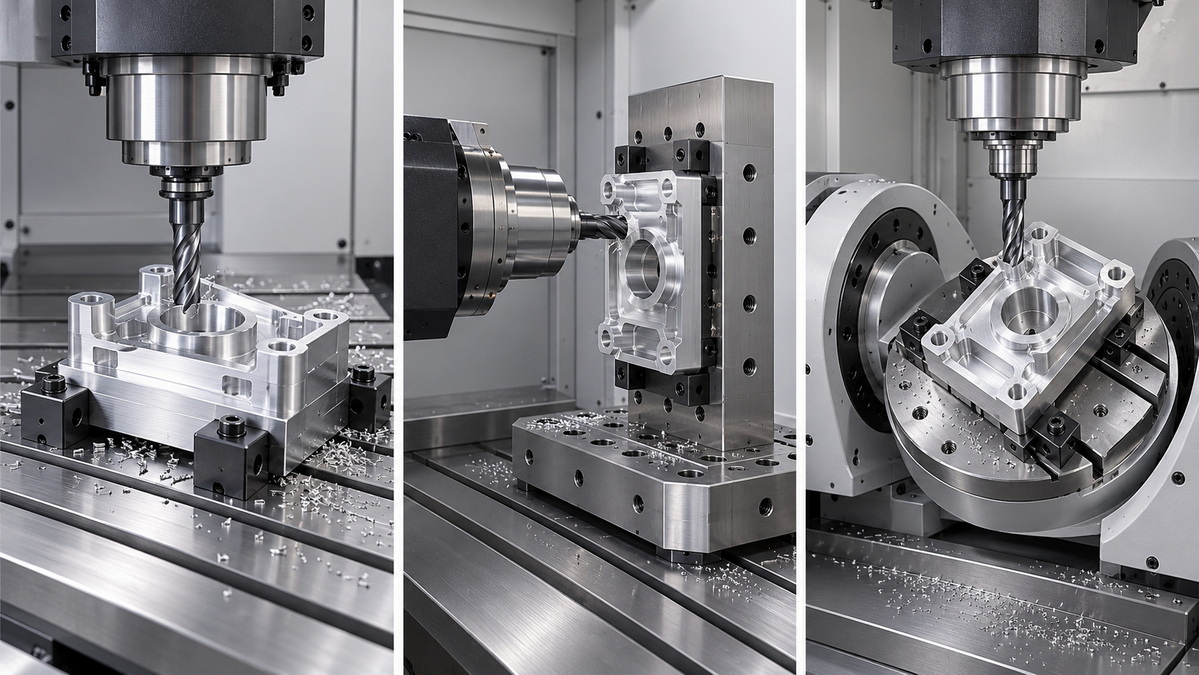
These methods use similar axis capabilities differently.
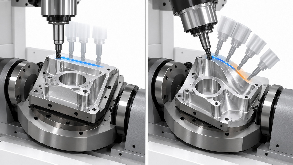
In 3+2 machining, the rotary axes position the component or tool at a selected angle. Cutting then proceeds with that orientation fixed.
In simultaneous five-axis machining, linear and rotary axes move together during cutting. This supports continuous changes in tool orientation along complex surfaces.
| Method | Typical purpose | Main consideration |
|---|---|---|
| Three-axis machining | Accessible surfaces, pockets, and holes | Some features require additional setups |
| 3+2 machining | Angled features and multi-sided access | Rotary positioning occurs between cutting sequences |
| Simultaneous five-axis machining | Complex surfaces requiring changing tool orientation | Programming, verification, and machine control become more demanding |
For procurement, ask which method the geometry actually requires. Paying for the most sophisticated process is not always the best route to a compliant component.
A conventional milling-based machining center can perform several related operations:
- Milling creates faces, slots, pockets, and contoured surfaces.
- Drilling produces holes.
- Boring enlarges and refines existing holes.
- Reaming finishes previously prepared holes.
- Tapping produces internal threads.
- Thread milling produces threads using a milling cutter.
Capability depends on tooling, programming, machine configuration, and access.
Grinding should not be presented as a standard function of every machining center. Abrasive processes require appropriate equipment or specialized configurations.
Likewise, turning normally belongs to a lathe or turning center. Mill-turn equipment combines capabilities, but a standard machining center should not be assumed to perform conventional turning.
A machining center is a type of CNC machine, not a synonym for every computer-controlled machine tool.
The term commonly describes a milling-based machine with automatic tool changing and the ability to perform multiple operations. A CNC mill may share these characteristics; terminology varies across equipment suppliers.
A turning center typically rotates the workpiece while tools remove material. It is especially relevant to cylindrical components, although configurations with live tooling can also perform milling and drilling.
Choose the process around the component. A shaft, pocketed housing, and formed sheet-metal enclosure may need very different manufacturing routes.
From a manufacturing-planning perspective, the useful question is not "Which machine is best?" It is "Which process can reliably produce this drawing at the required volume?"
Identify deep pockets, angled holes, thin walls, undercuts, and features on multiple faces.
Consider whether the cutting tool can reach each feature without excessive extension. Also check whether the fixture blocks important surfaces.
Material affects tool selection, cutting conditions, and heat management. Production quantity changes the economics of programming, fixtures, and automation.
A flexible setup may suit a prototype. A repeat order may justify dedicated workholding or a production arrangement that reduces loading time.
Evaluate more than cutting time. Include:
- Programming and setup.
- Material preparation.
- Fixture requirements.
- Tool changes and tool replacement.
- Deburring and cleaning.
- Secondary processing.
- Inspection and documentation.
A faster machining cycle can still produce a more expensive component if it creates additional handling or inspection work.
Machine positioning performance and finished-part compliance are related, but they are not interchangeable.
Tool deflection, clamping distortion, thermal variation, and tool wear can affect a component even when the machine operates correctly.
Datums are the reference features used to locate and measure other features. Manufacturing and inspection plans should interpret them consistently.
For a housing, the relationship between a mounting face and locating holes may matter more than an isolated dimension.
When installed and properly applied, machine probes can establish work offsets, check tool dimensions, detect broken tools, and measure selected features.
These functions help identify variation during production rather than waiting until every component is complete.
On-machine measurement is useful process feedback, but final acceptance should follow the agreed inspection plan.
Depending on the requirements, verification may involve gauges, micrometers, coordinate measurement, or surface-finish measurement. Buyers should specify which critical features require documented results.
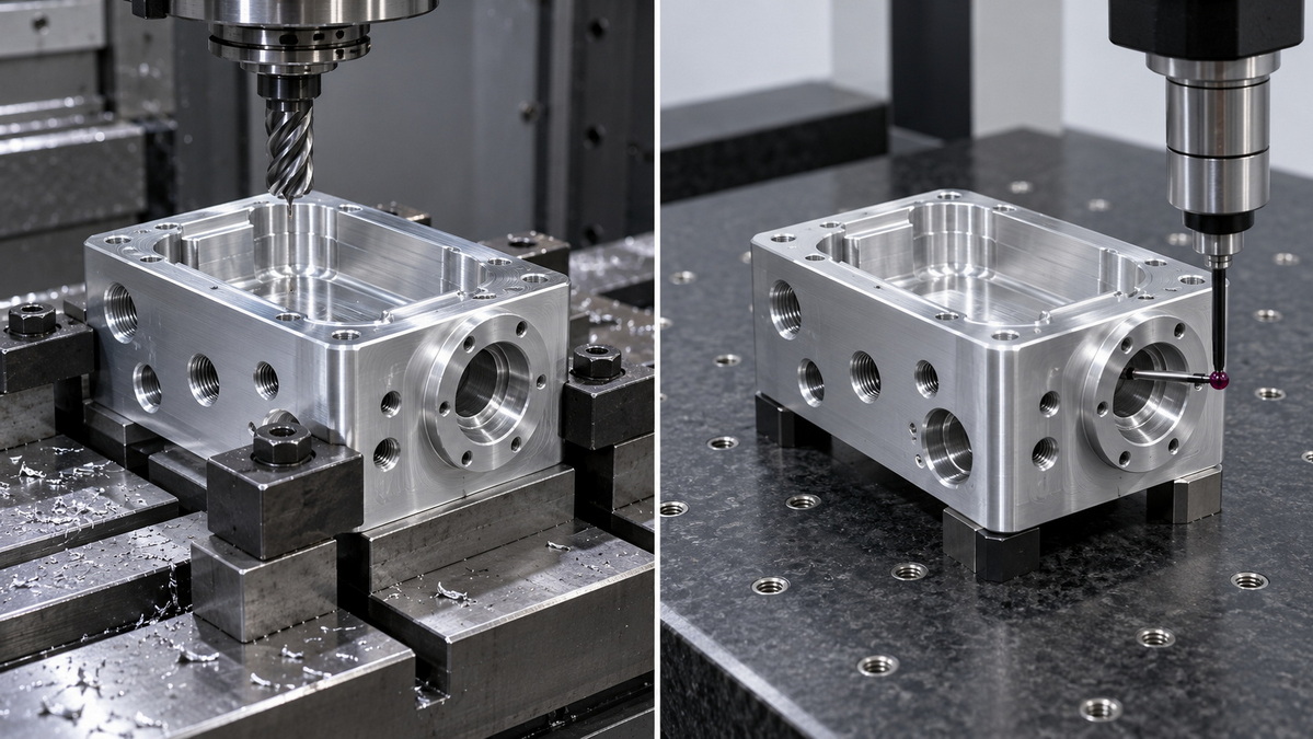
Consider an illustrative housing with a top pocket, side holes, and a locating bore referenced to its mounting face.
A three-axis route may require several setups. Each repositioning creates another opportunity for locating variation.
A 3+2 route may provide access to several faces with fewer repositioning steps, provided the fixture and machine travel allow it.
Before selecting either route, review:
1. Whether the clamping arrangement supports thin walls.
2. Whether tools can reach the pocket and side features.
3. How the locating bore relates to the drawing datums.
4. Which dimensions require verification after unclamping.
5. Whether the quantity justifies more elaborate workholding.
This is a planning example, not a reported customer result. Its lesson is that fewer setups are valuable only when the complete process remains stable and economical.
Machine purchase prices are not a reliable shortcut for estimating outsourced component prices.
Part cost depends on material, geometry, quantity, setup effort, machining time, tooling, finishing, inspection, and yield.
Tight requirements can increase cost when they require additional processing or verification. Apply demanding tolerances to functionally important features rather than specifying them indiscriminately.
To compare quotations fairly, provide every supplier with the same drawing revision, material specification, quantity, surface requirements, and inspection expectations.
Ask what the quotation includes. An apparently lower price may exclude finishing, documentation, packaging, or other necessary work.
U-Need positions itself as a precision manufacturing partner in China for global brands, distributors, and manufacturers.
Its stated service scope includes:
- Custom precision parts machining.
- Mold manufacturing, including injection molds, stamping dies, and cold-forging dies.
- Sheet metal fabrication, including laser cutting, bending, and stamping.
These processes solve different problems. Machining may suit detailed solid components, while sheet metal fabrication may be more appropriate for formed enclosures. Mold and die manufacturing supports separate production routes.
For a useful project review, provide a 3D model, dimensioned drawing, material specification, order quantity, finishing requirements, and target delivery date. Request confirmation of the proposed process and project-specific capabilities.
Send U-Need your drawings, material requirements, quantities, and critical dimensions to request a project-specific manufacturing review and quotation.
Ask the team to confirm the production route, inspection scope, secondary processes, and delivery assumptions before approving the order. Clear requirements give both sides a stronger foundation for dependable results.
No. CNC describes a broader category of computer-controlled equipment. A machining center is generally a milling-based CNC machine with automatic tool changing and multiple-operation capability.
No. Pallet changing depends on the machine configuration. Confirm whether the proposed equipment includes this function rather than assuming it is standard.
Yes, suitable configurations can machine metals and engineering plastics. Tooling, workholding, cutting conditions, and inspection methods must match the material and component requirements.
No. Additional axes improve access and may reduce setups, but finished accuracy still depends on machine condition, programming, tooling, fixturing, temperature, and verification.
Provide the drawing and model, material, quantities, tolerances, finish requirements, delivery expectations, and inspection needs. Identify critical features and the current drawing revision.
No. Turning, grinding, electrical discharge machining, forming, and molding may better suit particular geometries or production requirements. Some components require a combination of processes.
1.TOPS Precision — "What is a Machining Center? Types, Components & Industrial Applications." Original article reviewed and restructured; its generalized equipment, operation, and pricing statements were not adopted without qualification. [topsbest-precision]
2.Haas Automation — "5-Axis Machining Simplified." Technical basis for distinguishing indexed 3+2 machining from simultaneous five-axis movement. [haascnc]
3.Makino — "Horizontal 5-Axis." Manufacturer information on horizontal machining configurations, chip handling, and automation options. [makino]
4.Renishaw — "Probing and Tool Measurement Systems for Machine Tools." Technical support for workpiece setup, tool setting, offset updates, and broken-tool detection. [renishaw]
5.Renishaw — "Machine Tool Probes for Workpiece Set-up and Inspection." Technical support for in-process measurement, variation control, and part verification. [renishaw]


