Views: 244 Author: U-Need Publish Time: 2026-08-26 Origin: Site
Content Menu
● When CNC Machining Is the Right Manufacturing Method
● Understanding 3-Axis, 4-Axis, and 5-Axis CNC Machining
● Design for Manufacturability in CNC Machining
>> Use Tight Tolerances Only Where They Matter
>> Avoid Deep and Narrow Pockets
>> Standardize Holes and Threads
>> Use GD&T for Functional Relationships
● CNC Machining Materials and Their Applications
● Surface Finishes for CNC Machined Parts
● Quality Control for Precision CNC Machining
● From Prototype to Production: A Practical Manufacturing Workflow
>> 2. Manufacturability Review
>> 3. Quotation and Process Planning
>> 4. First Article Production
>> 5. Production and In-Process Control
>> 6. Final Inspection and Delivery
● A CNC Machining Project Checklist
● Precision Manufacturing Beyond CNC Machining
>> What is CNC machining used for?
>> What tolerance can CNC machining achieve?
>> What is the difference between 3-axis and 5-axis CNC machining?
>> Which materials can be CNC machined?
>> How can I reduce CNC machining costs?
>> Is CNC machining suitable for mass production?
>> What information is needed for a CNC machining quotation?
CNC machining is one of the most reliable manufacturing methods for producing precision metal and plastic parts. It gives product teams the flexibility to move from a CAD model to functional prototypes and repeat production without the large upfront tooling investment required by many forming processes.
For global brands, distributors, and manufacturers, successful CNC machining is not only about choosing a capable machine shop. It is about converting functional requirements into a manufacturable design, realistic tolerance plan, suitable material choice, and clear inspection standard.
U-Need supports customers with custom precision parts machining, mold manufacturing, sheet metal fabrication, and tooling solutions. Our approach focuses on helping customers make informed manufacturing decisions from the first prototype through stable production.
CNC machining means computer numerical control machining. It is a subtractive manufacturing process that removes material from a solid workpiece to create a finished part.
The process normally starts with a 3D CAD model. Manufacturing engineers use CAM software to convert the design into machining instructions. The CNC machine follows these programmed instructions to control cutting tools, spindle speed, feed rate, workholding, and movement across different axes.
Typical CNC operations include:
- Milling
- Turning
- Drilling
- Boring
- Tapping
- Reaming
- Thread milling
- Surface finishing
- Contouring
CNC machining is widely used because it can deliver accuracy, repeatability, material flexibility, and strong mechanical performance. Since the part is machined from solid material stock, it retains the properties of the selected metal or engineering plastic.
CNC machining is commonly used for:
- Functional prototypes
- Custom industrial parts
- Aerospace components
- Automotive fixtures
- Medical-device components
- Robotics parts
- Consumer-product housings
- Electronics enclosures
- Automation equipment
- Replacement and maintenance parts
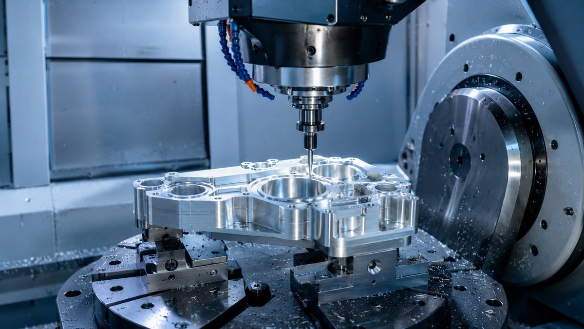
CNC machining is highly versatile, but it is not always the lowest-cost process for every part. The best manufacturing method depends on part geometry, material, annual volume, tolerance requirements, tooling budget, and delivery schedule.
| Manufacturing Requirement | Why CNC Machining Is Suitable | Another Process to Consider |
|---|---|---|
| One-off prototype | No mold or die is required | 3D printing for visual models |
| Precision metal component | Strong material properties and controlled dimensions | Grinding for ultra-fine surfaces |
| Low-volume production | Avoids major tooling investment | Casting for higher repeat volume |
| Complex multi-face geometry | Multi-axis machining improves feature access | Investment casting for suitable shapes |
| Engineering plastic part | Uses production-grade plastic materials | Injection molding for high-volume demand |
| Customized industrial component | Fast design changes and controlled production | Sheet metal fabrication for suitable structures |
For example, an aluminum electronics housing may be CNC machined for early testing because the design is still evolving. If demand rises and the housing geometry is appropriate, a later transition to die casting or extrusion may reduce the unit cost.
The best process is the one that supports the entire product lifecycle. A lower initial unit price can become expensive if it creates tooling delays, inconsistent quality, assembly issues, or repeated design revisions.
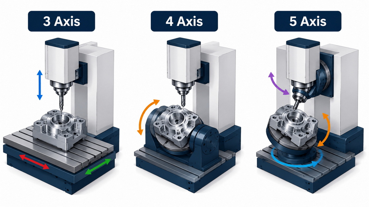
The number of machine axes affects tool access, setup complexity, machining efficiency, and the types of geometry that can be produced.
A 3-axis CNC machine moves the cutting tool along the X, Y, and Z axes. It is ideal for components with features that can be accessed from the top or through a limited number of repositioning operations.
Typical 3-axis applications include:
- Mounting plates
- Brackets
- Flat panels
- Basic enclosures
- Fixtures and jigs
- Simple housings
- Pockets, slots, and holes
- Machined plates with threaded features
3-axis machining is often the most economical option for parts with straightforward geometry and accessible features.
A 4-axis CNC machine adds a rotary axis. The workpiece can rotate during machining, allowing tools to access multiple sides more efficiently.
This process is useful for:
- Cylindrical features
- Radial holes
- Circular patterns
- Cam profiles
- Shafts and rotational components
- Parts with repeated side features
By reducing manual repositioning, 4-axis machining can improve production efficiency and reduce handling time.
A 5-axis CNC machine uses three linear axes plus two rotational axes. This gives the cutting tool access to complex angles and hard-to-reach features.
5-axis machining is suitable for:
- Aerospace components
- Robotics parts
- Medical components
- Complex housings
- Impellers and turbine-like geometries
- Deep angled cavities
- Curved surfaces
- Parts with multiple critical surfaces
- High-precision components requiring fewer setups
A major advantage of 5-axis machining is not simply that it can make more complicated shapes. It can also reduce the number of setups required to complete a part. Fewer setups can improve alignment between critical features and reduce the chance of error caused by repeated refixturing.
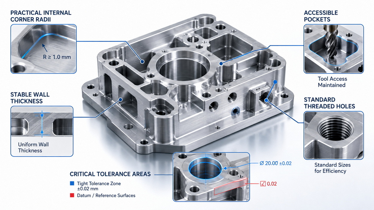
Good design for manufacturability helps improve production stability, reduce unnecessary machining time, and prevent avoidable cost increases.
A manufacturable part does not need to be simple. It needs to be designed with realistic access for cutting tools, sensible tolerances, and a clear understanding of how the part will be held and inspected.
Tolerances define the acceptable variation of a dimension. A tight tolerance may be necessary for a bearing seat, sealing surface, press-fit feature, or critical alignment hole. However, applying tight tolerances to non-critical dimensions increases machining and inspection effort.
For many standard machined components, general tolerances may be around ±0.1 mm to ±0.13 mm, depending on the material, part geometry, dimensions, machine setup, and inspection requirements.
Tighter tolerances may be required for:
- Bearing bores
- Shaft diameters
- Press-fit features
- Sliding mechanisms
- Sealing surfaces
- Mating faces
- Alignment holes
- Critical threads
- Precision optical or medical interfaces
Specify accuracy where function demands it. This creates a more practical balance between performance, lead time, and cost.
CNC milling cutters are round. They cannot create perfectly sharp internal corners in standard milling operations.
Adding internal corner radii makes the part easier to machine and can improve surface quality. Larger radii often allow the use of larger, more rigid cutting tools, which can remove material more efficiently.
When designing internal pockets:
- Avoid perfectly sharp internal corners
- Use practical corner radii
- Consider the depth of the pocket
- Allow enough space for cutting tools
- Review deep corners with the manufacturing engineer
Deep pockets require longer cutting tools. Long tools are less rigid and more likely to vibrate during machining. This can increase machining time and affect dimensional consistency or surface finish.
Before finalizing a deep cavity, consider whether you can:
- Reduce cavity depth
- Increase the pocket width
- Improve tool access from another side
- Divide the component into two parts
- Use a different manufacturing process
- Change the geometry to support multi-axis machining
Thin walls can flex under cutting forces. This is especially important for aluminum parts, engineering plastics, and tall wall features.
The practical wall thickness depends on material, wall height, adjacent geometry, machining method, and the part's final application. A manufacturing review is particularly valuable when a design includes thin ribs, high walls, or delicate structures.
Standard threads, hole sizes, and hardware simplify production and reduce sourcing risk.
When defining threaded features:
- Use common thread sizes whenever possible
- Identify through threads and blind threads clearly
- Define required thread engagement
- Avoid excessively deep blind threads
- Keep threads away from very thin walls
- Specify thread class when the application requires it
- Provide a clear note for inserts, helicoils, or special fasteners
Geometric dimensioning and tolerancing, often called GD&T, helps define how features relate to each other. It is particularly useful when a component has critical requirements for position, flatness, perpendicularity, profile, or concentricity.
GD&T is most valuable when it communicates functional intent clearly. It should not be added simply to make a drawing appear more complicated.
For example, a hole pattern may require a positional tolerance relative to a datum surface because the holes must align with mating components. A simple ± dimension may not fully communicate that assembly requirement.
Material selection has a major effect on part performance, machining time, surface finish, corrosion resistance, weight, and cost.
| Material | Key Characteristics | Typical Uses |
|---|---|---|
| Aluminum 6061 | Lightweight, corrosion-resistant, easy to machine | Housings, fixtures, brackets, electronics |
| Aluminum 7075 | Higher strength than 6061 | Aerospace and performance parts |
| Stainless Steel 303 | Good machinability and corrosion resistance | Shafts, fittings, industrial components |
| Stainless Steel 304 | Strong corrosion resistance | Food equipment, medical, marine applications |
| Stainless Steel 316 | Enhanced corrosion resistance | Chemical, marine, and medical environments |
| Carbon Steel | Strong and economical | Industrial machinery and structural parts |
| Brass | Easy to machine, conductive, corrosion-resistant | Valves, connectors, fittings |
| Copper | Excellent thermal and electrical conductivity | Busbars, heat-transfer components |
| Titanium | High strength-to-weight ratio | Aerospace and medical parts |
| POM / Delrin | Low friction and dimensional stability | Bushings, gears, sliding components |
| Nylon | Tough and wear-resistant | Wear pads, rollers, industrial fixtures |
| Polycarbonate | High impact resistance | Covers, guards, transparent parts |
| PEEK | High temperature and chemical resistance | Medical, semiconductor, industrial parts |
Material selection should always consider the final working environment.
Ask these questions before selecting a material:
- Will the part face moisture, salt, chemicals, or outdoor exposure?
- Does it need high strength or low weight?
- Will it operate at elevated temperatures?
- Does it need electrical or thermal conductivity?
- Does the part require a cosmetic appearance?
- Will it receive anodizing, plating, painting, powder coating, or passivation?
- Does the part require regulatory compliance or material certification?
Surface finishing improves appearance, corrosion resistance, wear resistance, electrical properties, and product identification.
Common finish options include:
- As-machined finish
- Sandblasting
- Brushing
- Polishing
- Bead blasting
- Anodizing
- Hard anodizing
- Powder coating
- Painting
- Electroplating
- Black oxide
- Passivation
- Laser marking
- Silk screening
The right finish depends on the material and end-use requirements.
For example:
- Anodized aluminum is suitable for corrosion resistance and a durable decorative finish.
- Passivated stainless steel is often selected to improve corrosion performance after machining.
- Powder-coated sheet metal provides durable color and surface protection.
- Polished brass or stainless steel may be used for visible consumer or architectural components.
Finish requirements should be included in the drawing or quotation request. If color matters, specify the color code, gloss requirement, texture, masking areas, and cosmetic surface standard.
A CNC-machined part should be evaluated not only by appearance but by its ability to meet dimensional, functional, and documentation requirements.
A reliable quality-control process may include:
- Incoming material verification
- Material certification review
- First article inspection
- In-process dimensional checks
- Calibrated measuring instruments
- CMM inspection
- Thread gauge verification
- Surface-finish checks
- Final inspection reports
- Lot traceability
- Controlled packaging and labeling
- Nonconformance handling and corrective action
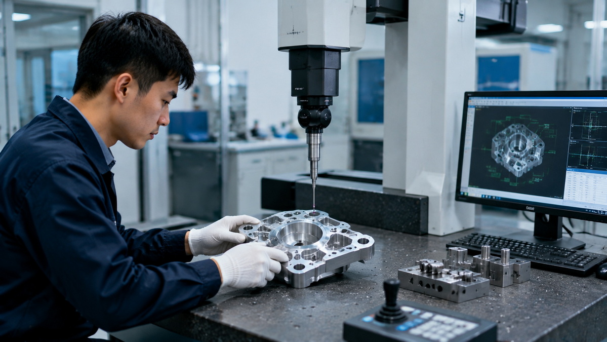
Coordinate measuring machines, commonly called CMMs, are used to inspect three-dimensional geometry. They can verify hole locations, profiles, flatness, positional relationships, and other critical dimensions that may be difficult to measure accurately with manual tools alone.
For projects with demanding requirements, define inspection expectations before production begins. The quotation should clarify whether the project requires:
- A standard inspection
- A dimensional inspection report
- A first article inspection report
- Material certificates
- Certificates of conformity
- Full lot traceability
- Customer-specific quality documentation
Clear inspection requirements prevent assumptions and improve communication across the supply chain.
A well-managed CNC project follows a controlled sequence. Each stage helps reduce the risk of design misunderstandings, production delays, and quality issues.
The process starts with a review of the CAD model, 2D drawing, material, surface finish, tolerance requirements, and application details.
The goal is to identify machining risks before production begins.
The manufacturing team evaluates part geometry, tool access, wall thickness, pocket depth, workholding, machining setups, and inspection feasibility.
This is the stage where design adjustments can prevent high cost or unstable quality.
After confirming the design requirements, the supplier prepares the manufacturing process, including machining method, material sourcing, tooling, inspection requirements, finishing, packaging, and lead time.
For new or critical parts, the first article is produced and inspected before full production begins.
This stage confirms that the manufacturing process can achieve the required dimensions and functional relationships.
Once the first article is approved, production proceeds according to the defined process. In-process checks help identify variation before it affects a full batch.
Completed parts are checked, documented as required, packaged securely, and prepared for shipment.
Before requesting a quotation, prepare the information that helps the manufacturing team evaluate the project accurately.
1. Provide a 3D CAD model in STEP, IGES, Parasolid, or another compatible format.
2. Provide a 2D drawing for critical dimensions, threads, tolerances, and GD&T.
3. Identify the required material grade and acceptable alternatives.
4. Specify the surface finish, color, coating, plating, or anodizing requirement.
5. Mark critical dimensions and functional features clearly.
6. State the required quantity and target delivery date.
7. Share the expected annual volume when available.
8. Define inspection and documentation requirements.
9. Explain the working environment when material selection is uncertain.
10. Confirm packaging, labeling, and shipping requirements.
The more complete the manufacturing information, the more accurate the process planning, quotation, and production outcome will be.
CNC machining is a valuable manufacturing solution, but many products require additional processes as they scale.
U-Need provides integrated manufacturing support across multiple production methods:
- Custom precision parts machining
- Injection mold manufacturing
- Stamping die manufacturing
- Cold-forging die manufacturing
- Laser cutting
- Sheet metal bending
- Metal stamping
- Welding and assembly support
- Surface finishing coordination
- Prototype and repeat production management
This combination allows manufacturers to review different process options based on part complexity, material, production volume, and total project cost.
For instance, a project may begin with CNC-machined samples, move to sheet metal fabrication for early market production, and later adopt stamping or molding once the design and forecast volume are stable.
CNC machining is used to produce precision parts from metal and plastic materials. Common applications include prototypes, industrial equipment components, medical parts, electronics housings, robotics components, automotive fixtures, aerospace parts, and custom mechanical assemblies.
Many standard CNC-machined parts use general tolerances around ±0.1 mm to ±0.13 mm. Tighter tolerances are possible when required, but they depend on part geometry, material, size, setup method, tooling, and inspection capability.
A 3-axis machine moves along three linear directions and is suitable for simple, accessible geometry. A 5-axis machine adds rotational movement, allowing the tool to reach complex angles and multiple surfaces with fewer setups.
CNC machining can process aluminum, stainless steel, carbon steel, brass, copper, titanium, POM, nylon, polycarbonate, PEEK, ABS, acrylic, and many other engineering materials.
You can reduce cost by using realistic tolerances, avoiding deep narrow cavities, including internal corner radii, standardizing hole sizes and threads, simplifying setups, selecting suitable materials, and completing a manufacturability review before production.
CNC machining is suitable for prototypes, low-volume manufacturing, bridge production, and many medium-volume applications. For very high-volume parts, injection molding, die casting, stamping, or forging may offer a lower unit cost after tooling investment.
A complete quotation request should include a 3D CAD file, 2D drawing, material requirements, tolerance information, surface finish, quantity, inspection needs, delivery schedule, and any packaging or labeling requirements.
1. RapidDirect. [CNC Machining White Paper]
2. Protolabs. [Understanding CNC Machining Tolerances]
3. Hubs. [How to Design Parts for CNC Machining]
4. International Organization for Standardization. [ISO 2768: Geometrical Product Specifications]
5. ASME. [Y14.5 Dimensioning and Tolerancing]
6. National Institute of Standards and Technology. [Introducing Xenos, NIST's Largest Coordinate Measuring Machine]
7. Protolabs. [Quality CNC Machined Parts]


