Views: 242 Author: U-Need Publish Time: 2026-07-18 Origin: Site
Content Menu
● Form Milling: How It Works and Why It Matters for Modern Manufacturing
● What Is Form Milling? An Engineer's Shop‑Floor Perspective
● Why Manufacturers Still Rely on Form Milling
● How Form Milling Works: From CAD to Finished Part
>> Step 1 – Design and Profile Definition
>> Step 2 – Translating CAD to CAM
>> Step 3 – Form Cutter Design and Manufacturing
>> Step 4 – Setup, Workholding, and Parameters
>> Step 5 – Cutting, Inspection, and Post‑Processing
● Common Types of Form Milling Cutters
● Key Applications of Form Milling in Industry
>> Automotive and Mobility Components
>> Aerospace and High‑Performance Structures
>> Tooling, Mold, and Die Manufacturing
>> General Manufacturing and Consumer Goods
● Comparing Form Milling with Other Milling Methods
>> Choosing the Right Milling Approach
● Advantages and Limitations in Real Production Environments
>> Advantages
>> Limitations
● How U‑Need Integrates Form Milling into End‑to‑End Manufacturing
>> Comprehensive Capability Stack
● Practical Design and Process Tips from an Industry Expert
● Summary and Partnering Insight
Form milling is a specialized CNC machining process that uses profile‑specific cutters to create complex contours, gear teeth, grooves, and precision features in a highly controlled operation. When you combine form milling with an experienced precision partner like U‑Need in China, you unlock repeatable, high‑tolerance production for global brands that need both speed and reliability.
Form milling is a type of milling where the cutter itself carries the final profile you want to transfer onto the workpiece. Instead of building up shapes through many small toolpath steps, the cutter's geometry directly defines the part surface — curves, radii, gear teeth, threads, or custom grooves.
In practice, a machinist mounts a dedicated form cutter on a CNC mill, aligns the workpiece, and lets the tool sweep across the material so its shape is "printed" into the part with high repeatability. This direct profile transfer makes form milling ideal for high‑volume production where thousands of identical profiles are required, such as gears, molds, and precision automotive components.
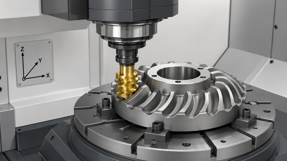
From an engineer's point of view, form milling is all about geometry control and consistency. The cutter profile is carefully designed or ground to match the required part contour; the machine then uses this cutter to remove material along a defined path. Because the cutter shape is fixed, the resulting parts share the same contour, as long as the process is stable.
This approach is especially powerful when the profile is complex but repeatable. Instead of programming intricate toolpaths for a standard end mill, a single dedicated cutter can generate the form in one or a few passes. That combination of precision and simplicity is why form milling remains a staple technique in demanding industries.
In modern manufacturing, form milling sits at the intersection of precision, efficiency, and scalability. Where standard milling might require multiple passes and frequent tool changes, form milling can often cut the entire profile with fewer operations.
Key reasons manufacturers invest in form milling include:
- Single‑pass shape generation for repeated contours and profiles.
- Consistent dimensional accuracy across large batches.
- Lower cost over time when the same profile is produced repeatedly.
- Versatility across materials such as steels, aluminum, copper alloys, and engineering plastics.
For export‑focused production, this repeatability is crucial. Large orders from automotive, tooling, and industrial customers depend on stable processes that deliver identical parts across multiple shipments.
Every successful form milling project starts with a clear digital design. Engineers create a 2D or 3D model of the desired contour, including radii, angles, and functional features. They also define tolerances, surface finish targets, and interface conditions with mating parts.
A key insight from real projects is that the cutter geometry must closely match the specified contour. While minor toolpath optimizations are possible, you cannot rely on software to fix a poorly designed cutter. Any deviation in the cutter shape tends to repeat on every manufactured part.
Once the design is finalized, CAM software converts the model into machine‑readable code. Engineers define toolpaths, feeds, and speeds, and simulate the cutting motion to check for collisions and interference.
Before cutting real material, experienced shops always perform a dry run to verify machine movements. This reduces scrap risk, especially when working with expensive alloys or hardened tool steels used in molds and dies.
Form milling cutters are typically made from high‑speed steel or carbide, selected according to cutting speed requirements and workpiece material. Toolmakers grind the cutter profile using precision grinding machines, ensuring that cutting edges match the design.
For demanding applications, cutters may incorporate carbide inserts that can be replaced or reground. This extends tool life and reduces overall cost, particularly in high‑volume production where tool wear is a major factor.
On the shop floor, workholding and alignment are critical. The workpiece must be clamped securely and located accurately in relation to the cutter. Any misalignment shows up directly in the machined contour.
Key parameters include:
- Spindle speed to balance heat generation and tool life.
- Feed rate to protect fragile edges on intricate cutters.
- Depth of cut to control deflection and achieve the desired surface finish.
- Coolant strategy to maintain temperature and help chip evacuation.
Well‑defined parameters and stable fixturing are essential to maintain profile accuracy throughout a production run.
With everything set, the CNC machine executes the programmed toolpath. As the form cutter sweeps across the workpiece, it shapes the material according to its profile.
Finished parts are inspected using gauges, templates, or coordinate‑measuring machines. In many cases, minor deburring or polishing is needed, but a well‑optimized form milling process minimizes extra finishing steps.
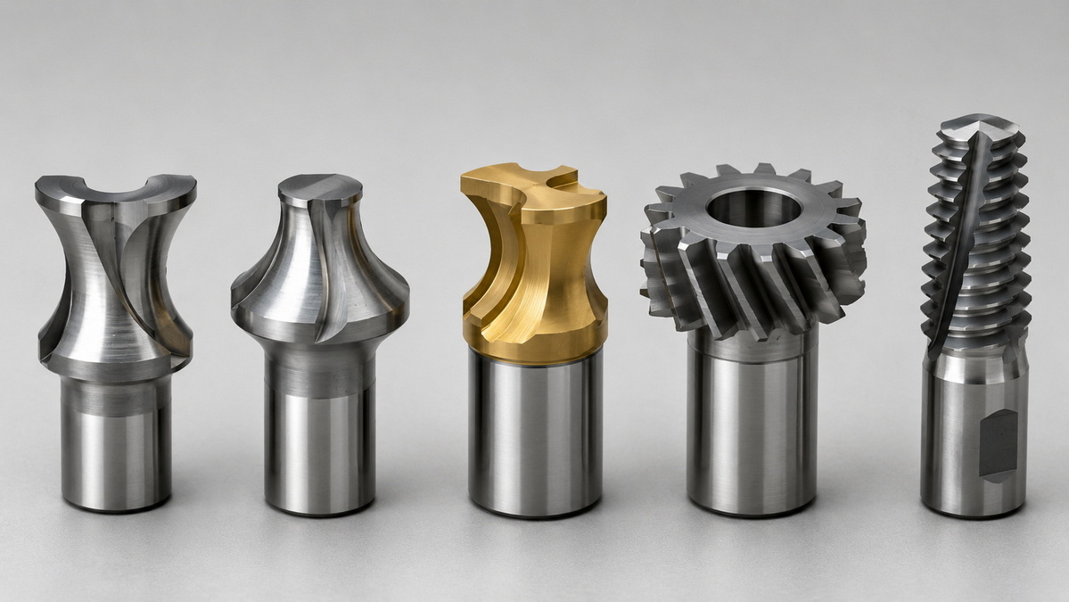
Different cutter types are used to support a wide range of applications:
- Concave and convex cutters for rounded edges and curved profiles.
- Corner‑rounding cutters for adding functional fillets and breaking sharp edges.
- Gear form cutters for involute tooth profiles used in transmissions and powertrains.
- Thread form cutters for milling threads directly into components when tapping is impractical.
Each cutter type is engineered around a specific geometry, which allows manufacturers to combine aesthetic design and mechanical performance in a single operation.
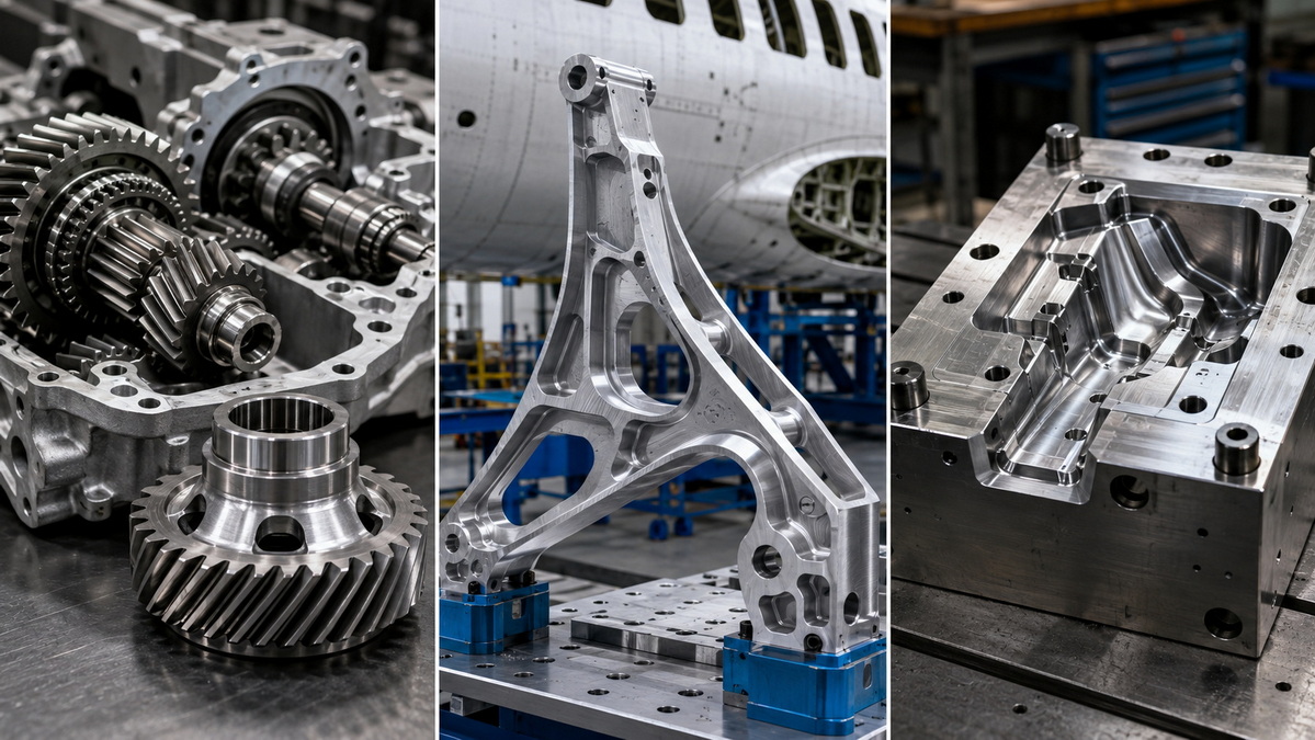
In automotive and mobility sectors, form milling is used for gears, splines, shafts, and couplings that must transmit power smoothly and reliably. Accurate tooth profiles reduce vibration and noise, while consistent production ensures long‑term performance in transmissions and driveline assemblies.
High‑volume orders benefit from the ability to machine thousands of identical profiles without reprogramming complex toolpaths, supporting stable quality across multiple batches.
Aerospace components often require tight tolerance control and consistent geometries on brackets, structural profiles, and certain turbine‑related features. Form milling supports these requirements by delivering repeatable contours that integrate into lightweight, high‑strength designs.
Because any deviation can affect structural behavior, reliable form milling processes contribute directly to long‑term performance and safety.
For mold makers and die shops, form milling is indispensable for creating cores, cavities, fillets, and beads in hardened tool steels. Direct profile generation reduces the number of setups and shortens lead time.
When combined with other machining operations, form milling helps deliver complete molds and dies that meet strict dimensional and surface finish requirements, supporting efficient production of plastic parts, stamped metal components, and forged pieces.
Form milling also supports the production of machine components, appliance parts, sporting goods, and furniture hardware. Complex shapes, decorative edges, and functional grooves can be machined efficiently once a dedicated cutter is available.
For manufacturers supplying multiple markets, this flexibility helps create distinctive product features while keeping production robust and repeatable.
Engineers often compare form milling with plain milling and end milling when selecting a process for a project.
| Milling Method | Best For | Main Strength | Typical Use Cases |
|---|---|---|---|
| Form milling | Complex repeated profiles | High efficiency and repeatability for identical contours | Gears, grooves, rounded edges, molds, dies |
| Plain milling | Large flat surfaces | Simple setup and fast face machining | Base plates, machine beds, flat faces |
| End milling | Cavities and multi‑feature parts | Flexible toolpaths for varied geometries | Pockets, slots, 3D contours in molds and structural parts |
A practical rule is: choose form milling when you need the same intricate profile many times; use end milling when features vary or the design is still evolving; rely on plain milling for straightforward flat surfaces and stock removal.
Seasoned production managers appreciate form milling for several reasons:
- High precision and tight tolerances for complex contours and gear profiles.
- Efficiency in high‑volume runs, with fewer tool changes and reduced machining steps.
- Lower cost over the life of a project when the same profile is repeated.
- Improved surface quality, as profile‑matched cutters minimize toolpath marks.
These strengths make form milling a go‑to solution for stable part designs that will be produced over extended periods.
However, there are practical limitations that need to be considered:
- Higher upfront tool cost, as cutters are profile‑specific and often custom‑ground.
- Reduced flexibility once a cutter is made; significant design changes may require new tooling.
- Lead time for specialized tooling, especially with complex geometries or carbide inserts.
This balance means form milling is best suited to projects where design stability and production volume justify the initial investment in dedicated tools.
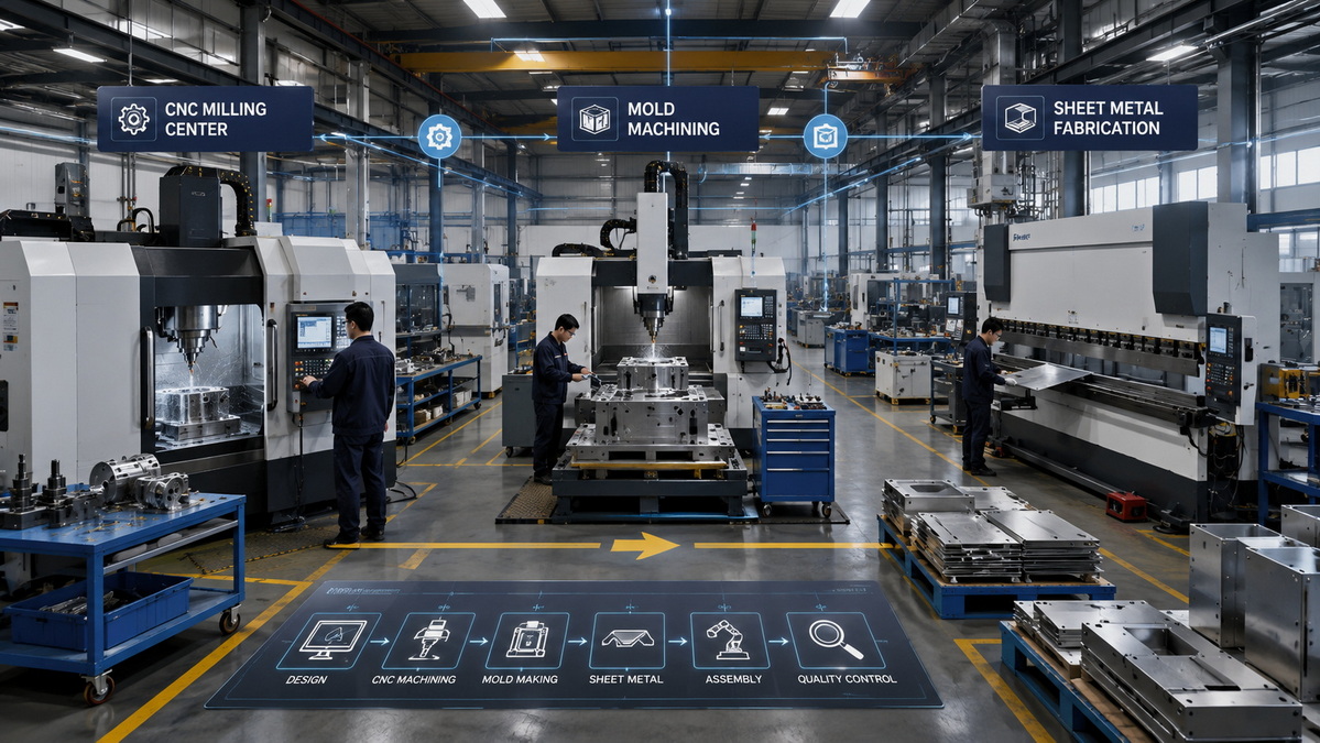
U‑Need serves global brands, distributors, and manufacturers as a precision manufacturing partner in China, combining form milling with a wider range of capabilities to deliver complete solutions.
By integrating multiple processes under one roof, U‑Need can take a project from concept to finished parts efficiently:
- Custom precision parts machining for dimensional accuracy on critical features.
- Form milling for gear teeth, radiused edges, grooves, and contour surfaces that must repeat consistently.
- Mold manufacturing, including injection molds, stamping dies, and cold‑forging dies, where form‑milled shapes define cavity and core performance.
- Sheet metal fabrication, such as laser cutting, bending, and stamping, to produce housings and enclosures that interface with machined components.
This integration reduces coordination complexity for international buyers and helps ensure that mating parts are produced with aligned dimensional and process controls.
To make the most of form milling in real projects, engineers and sourcing managers can follow several practical guidelines:
1. Lock the profile early in the design phase. Because form cutters are custom, late profile changes can be costly and time‑consuming.
2. Specify realistic tolerances. Match tolerance levels to functional needs rather than defaulting to unnecessarily tight limits.
3. Design for tool access. Avoid undercuts or obstructed regions that the cutter cannot reach without complex fixtures.
4. Standardize profiles when possible. Reusing form cutter geometries across part families increases the return on tooling investment.
5. Plan for tool maintenance. Work with suppliers that can regrind cutters or replace inserts to extend tool life.
These steps help bridge the gap between digital design and production reality, keeping projects on schedule and within budget while maintaining quality.
Form milling remains a powerful technique for creating precise, repeatable profiles on gears, molds, structural components, and a wide variety of industrial parts. By using dedicated cutters that carry the required geometry, manufacturers can achieve tight tolerances and high efficiency in high‑volume production.
When this process is combined with comprehensive machining, mold manufacturing, and sheet metal capabilities, it becomes part of a robust end‑to‑end solution. U‑Need's experience in precision manufacturing and its integrated service offering make it well placed to support global customers that depend on consistent quality, reliable delivery, and long‑term production stability.
Q1: When is form milling the best choice for a project?
Form milling is ideal when you need the same complex profile across many parts, such as gears, splines, grooves, or mold cavities, and when long‑term dimensional consistency is critical.
Q2: What materials can be processed effectively with form milling?
Form milling can be applied to steels, aluminum alloys, copper‑based materials, and engineering plastics, provided cutter materials and cutting parameters are selected correctly.
Q3: Is form milling suitable for prototyping?
It can be used in prototyping, but it is most cost‑effective in projects where designs are stable and production volumes justify the investment in custom cutters.
Q4: How precise can form milling be?
With appropriate tooling, machine setup, and inspection, very tight tolerances can be achieved, making form milling suitable for critical components in transmissions, tooling, and structural applications.
Q5: What information should be provided when requesting form milling services?
For accurate quotations and process planning, provide detailed CAD models, material specifications, tolerance requirements, expected volumes, and any special surface finish or heat‑treatment needs.
1.RapidDirect. "What's Form Milling and How Does it Work?" – https://www.rapiddirect.com/blog/form-milling-how-it-works/
2.3ERP. "What is Form Milling: Definition, Process and Applications." – https://www.3erp.com/blog/form-milling/
3.Xometry. "Form Milling: How It Works, Types, Advantages, and Applications." – https://www.xometry.com/resources/machining/form-milling/
4.JLCCNC. "Form Milling: Process, Cutters, and Applications." – https://jlccnc.com/blog/form-milling
5.Stecker Machine. "What is Form Milling? How is it Done? What is it Used For?" – https://www.steckermachine.com/blog/what-is-form-milling
6.DEK. "Form Milling: Types, Process, and Applications." – https://www.dekmake.com/form-milling/
7.VMT. "What is Form Milling? How Does it Work?" – https://vmtcnc.com/what-is-form-milling


