Views: 238 Author: U-Need Publish Time: 2026-11-01 Origin: Site
Content Menu
● What Is Tight Tolerance Machining?
>> Dimensional Tolerances Do Not Describe Everything
● When Are Tight CNC Machining Tolerances Necessary?
● Why Tight Tolerance Machining Becomes Difficult
>> Material Behavior Changes the Process
>> Clamping Can Hide Distortion
>> Tool Wear Creates Dimensional Drift
● Temperature Control: A Small Change With a Measurable Effect
● A Six-Step Workflow for Reliable Precision Parts
>> 1. Review the Drawing Before Cutting
>> 2. Build the Process Around Critical Features
>> 3. Separate Roughing From Finishing
>> 4. Match Tooling to Geometry and Material
>> 5. Inspect During Production
>> 6. Verify the Finished Condition
● Inspection: Choose Evidence, Not Just Equipment Names
>> Agree on Borderline Results
● Batch Consistency: What Cp and Cpk Actually Tell Buyers
● How to Reduce Tight Tolerance Machining Costs
● Preparing a Tight Tolerance Machining Request for U-Need
>> What is considered a tight machining tolerance?
>> Can CNC machining achieve ±0.005 mm?
>> Are tighter tolerances always better?
>> Is a CMM required for every precision part?
>> Should critical dimensions be checked after coating?
>> What should I request besides an inspection report?
Tight tolerance machining keeps critical part dimensions within narrow specified limits so components fit, move, seal, and perform as intended. For global brands, distributors, and manufacturers sourcing custom precision parts, success requires more than an accurate CNC machine. Material behavior, workholding, temperature, inspection, and drawing clarity all influence whether a part meets its requirements consistently.
At U-Need, our starting point is function: which features determine whether your assembly works? That question helps separate necessary precision from specifications that increase cost without improving performance.
This guide explains how to define tight machining tolerances, manage production risks, and prepare a clearer manufacturing request.
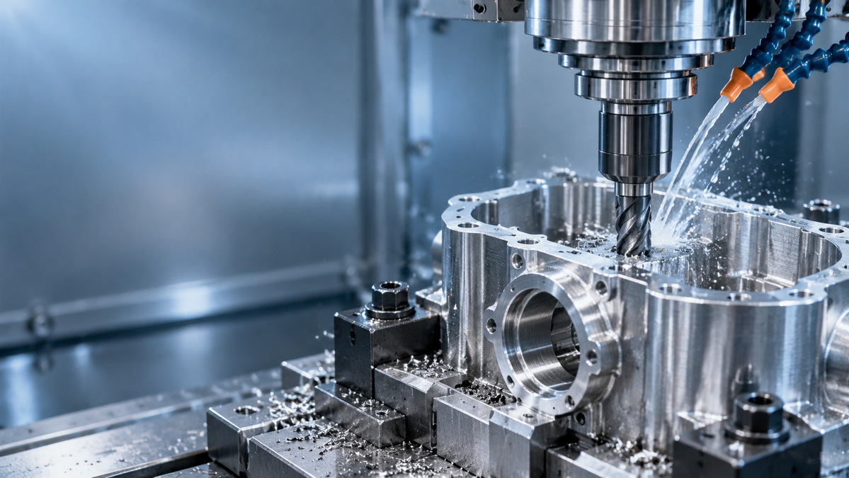
A machining tolerance defines the permitted variation from a specified dimension. Tight tolerance machining controls that variation within a narrow range appropriate to the component's application.
For example, a shaft specified as 20.000 ±0.005 mm may measure between 19.995 and 20.005 mm. Its total tolerance zone is 0.010 mm, or 10 micrometers.
There is no single numerical threshold that makes every tolerance "tight." Difficulty depends on:
- Part size and geometry.
- Material and heat-treatment condition.
- Feature accessibility and wall thickness.
- Required surface finish and geometric accuracy.
- Production quantity and inspection requirements.
A tolerance achievable on a short, rigid shaft may be difficult on a long, thin-walled housing.
Size alone does not guarantee assembly performance.
A bore can meet its diameter requirement while having unacceptable roundness or an incorrect location relative to another feature. Depending on function, drawings may also need controls for flatness, perpendicularity, position, or runout.
Surface roughness is another separate requirement. A dimensionally acceptable sealing surface may still perform poorly if its texture is unsuitable.
Specify these characteristics individually rather than expecting a tight size tolerance to control them all.
Tighter limits are useful when dimensional variation directly affects a functional interface.
| Application | Critical concern | Specification focus |
|---|---|---|
| Shaft-and-bearing assembly | Fit and alignment | Diameter, form, and relevant runout |
| Sealing interface | Leakage or uneven contact | Flatness, geometry, and surface texture |
| Locating fixture | Repeatable component positioning | Datum relationships and feature position |
| Mold or die assembly | Alignment and working clearance | Mating geometry and critical dimensions |
| Precision housing | Consistent assembly | Bore location and interface dimensions |
The practical approach is selective precision. Identify critical-to-function features, then apply suitable general tolerances elsewhere.
Before tightening a requirement, ask: what failure would occur if this feature varied more? A clear answer helps justify both the manufacturing route and inspection effort.
Material selection affects cutting forces, heat generation, tool wear, and dimensional stability.
Titanium, for example, is not automatically an easy material for high-precision machining. Its poor thermal conductivity concentrates heat near the cutting zone, increasing demands on tooling, coolant delivery, and setup rigidity.
Thin aluminum walls present a different challenge: low stiffness can allow movement under cutting or clamping forces.
Discuss the exact alloy, stock condition, and final geometry rather than relying on broad labels such as "steel" or "aluminum."
A component may measure correctly while clamped, then move after release.
This is especially important for thin walls, open frames, and parts with substantial material removal. Excessive clamping force can temporarily deform a feature, while unbalanced machining can release internal stresses unevenly.
Useful controls include supported fixtures, controlled clamping, staged roughing, and inspection in the agreed free or restrained condition.
A new cutting edge and a worn cutting edge do not behave identically. Progressive wear can change cutting forces, surface quality, and feature size.
For repeat production, the process should define when tools are checked, adjusted, or replaced. Waiting until a dimension fails leaves less opportunity to prevent scrap.
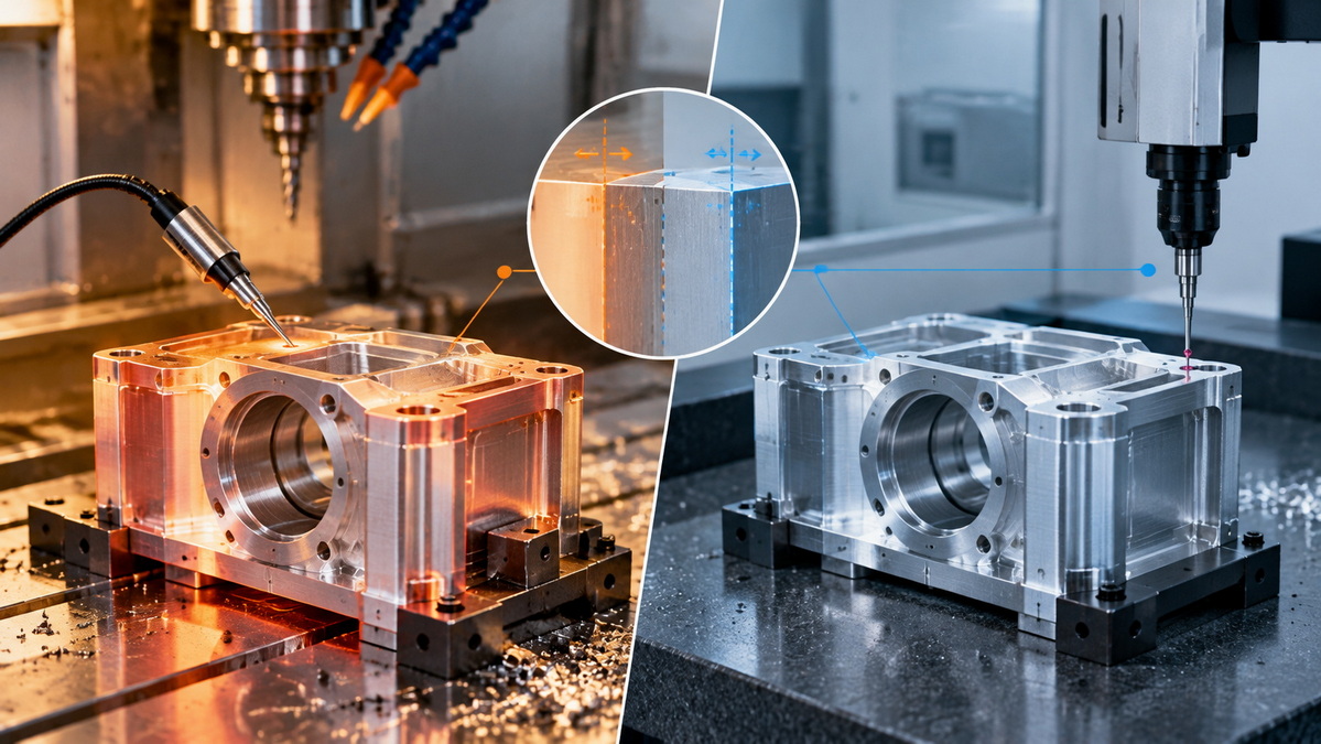
Dimensional measurements conventionally refer to a temperature of 20°C. Measurements made elsewhere require consideration of thermal expansion and the uncertainty associated with temperature and material properties.
Consider this illustrative calculation:
- Component length: 100 mm.
- Assumed thermal expansion coefficient: 23 µm/m/°C.
- Temperature difference: 5°C.
That change exceeds the entire tolerance zone of the earlier ±0.005 mm example.
This is an engineering illustration, not a certified material value or a U-Need production result. Actual expansion depends on the alloy and temperature range.
A precision process should consider:
1. Consistent machine warm-up.
2. Coolant and workshop temperature stability.
3. Adequate equilibration before final inspection.
4. Part temperature during measurement.
5. Thermal correction where appropriate.
Room temperature alone is not enough. A recently machined component may still be warmer than its surroundings.
Begin with the drawing revision, units, datum scheme, material, and critical features.
Resolve conflicts between the three-dimensional model and two-dimensional drawing before production. Clarify whether requirements apply before or after coating, heat treatment, or other secondary operations.
This review establishes a common acceptance standard.
Identify which dimensions must remain related to one another.
Where practical, machine related features in one setup to reduce transfer errors. When multiple setups are necessary, establish repeatable locating surfaces and protect them throughout production.
The objective is not simply fewer setups. It is a controlled relationship between machining operations and functional datums.
Roughing removes most of the stock. Finishing establishes final dimensions and surface condition.
For distortion-sensitive components, an intermediate stage may allow inspection, stabilization, or appropriate stress-relief treatment before final machining.
Finishing allowance must also be controlled. An inconsistent allowance changes cutting conditions and can undermine repeatability.
Choose tool geometry, cutting parameters, and coolant strategy for the actual application.
Short, rigid tool assemblies generally reduce deflection risk. Deep pockets and inaccessible features may require longer tools, creating a different stability challenge.
Avoid assuming that slower cutting or shallower passes always improve accuracy. Parameters must work together rather than being adjusted in isolation.
Check critical characteristics while correction remains possible.
A useful plan can include first-piece approval, scheduled in-process checks, and additional verification after tool changes or setup adjustments.
For higher-volume orders, monitoring measurement trends can reveal drift before dimensions reach their limits.
Final inspection should reflect the delivered part.
Where secondary operations can alter dimensions, include the relevant post-process checks. Record the drawing revision, inspection method, and acceptance results so the manufacturing and purchasing teams evaluate the same requirements.
A coordinate measuring machine can inspect many dimensional and geometric characteristics, but it is not automatically the best instrument for every feature.
The method must suit the tolerance, geometry, accessibility, and measurement uncertainty.
| Inspection method | Typical use | Important consideration |
|---|---|---|
| Micrometer | Accessible external dimensions | Contact force, alignment, and temperature |
| Bore gauge | Internal size comparisons | Setting reference and technique |
| Coordinate measuring machine | Feature locations and geometric relationships | Probing strategy, setup, and uncertainty |
| Surface texture instrument | Specified roughness characteristics | Evaluation settings and measurement direction |
Digital resolution is not the same as measurement accuracy. More displayed digits do not prove that an instrument can reliably judge a narrow tolerance.
Every measurement has uncertainty. A reading close to a specification limit may therefore require more careful interpretation than a simple pass/fail display suggests.
For critical features, agree on the measurement method and acceptance decision rule before production. This reduces disagreements when supplier and customer measurements differ slightly.

One acceptable prototype does not demonstrate repeatable production.
Process capability compares a stable process's variation with its specification limits. Two commonly used indices are:
- Cp, which compares tolerance width with process spread.
- Cpk, which also considers how far the process mean sits from the nearest limit.
Consider an illustrative feature with limits of 9.990 and 10.010 mm. If the process standard deviation is 0.002 mm, Cp is approximately 1.67.
If the mean shifts to 10.004 mm, Cpk falls to 1.00 even though the spread remains unchanged.
The lesson is straightforward: a relatively narrow distribution can still produce risk when it moves toward a specification boundary.
Capability figures require suitable data, a stable process, and appropriate statistical assumptions. They should not be presented as universal guarantees or calculated from a few selected good parts.
The most useful cost question is not "How tight can this be?" It is "How much precision does this function require?"
Review these opportunities before requesting quotations:
- Apply narrow limits only to functional features.
- Avoid unnecessarily deep pockets and thin walls.
- Use practical internal radii where the design permits.
- Clarify coating thickness and finished dimensions.
- Consider the accumulated variation across mating parts.
- Match inspection documentation to actual risk.
Ask suppliers to explain cost drivers rather than comparing unit prices alone. Different quotations may assume different inspection frequencies, secondary operations, or acceptance conditions.
A slightly lower machining price offers little value if the delivered parts require sorting, rework, or assembly changes.
U-Need supports global brands, distributors, and manufacturers with custom precision parts machining, mold manufacturing, and sheet metal fabrication in China. Its stated service scope includes injection molds, stamping dies, cold-forging dies, laser cutting, bending, and stamping.
For a more useful technical discussion, provide:
1. A current three-dimensional model and dimensioned drawing.
2. Material grade and required condition.
3. Prototype quantity and expected repeat demand.
4. Critical dimensions, datums, and mating-part information.
5. Surface finish, coating, and heat-treatment requirements.
6. Inspection reports and traceability requirements.
7. Target delivery schedule.
Send your drawings to U-Need and identify the features that determine fit, sealing, movement, or alignment. Request a manufacturability review and quotation that explicitly addresses those requirements.
Any achievable tolerance, inspection arrangement, or delivery commitment should be confirmed for the specific project.

There is no universal cutoff. A tolerance becomes demanding when its permitted variation approaches the practical limits of the material, geometry, manufacturing process, or inspection method.
It may be achievable for suitable features under controlled conditions. It should not be assumed for every material, size, or geometry. Confirm feasibility and verification methods against the actual drawing.
No. Unnecessarily narrow limits can increase machining, inspection, and rejection costs without improving the assembly. Specify precision according to functional need and the combined variation of mating components.
No. Instrument selection depends on the characteristic being measured. A suitable micrometer, bore gauge, or dedicated gauge may be more appropriate for some features.
Yes, when the requirement applies to the coated part. Define the finished condition clearly because coatings and secondary processes can affect fit and measurable dimensions.
For critical repeat orders, consider requesting the inspection method, agreed sampling frequency, calibration traceability, and relevant process-control evidence. Establish these requirements before comparing quotations.
1. [TOPS — "Tight Tolerance Machining: 13 Tips to Achieve It"]. Original article reviewed for topic coverage, structure, and technical gaps. Its claims were not adopted without qualification. [topsbest-precision]
2. [National Institute of Standards and Technology — "Uncertainties in Dimensional Measurements Made at Nonstandard Temperatures"]. Technical basis for the 20°C reference temperature and temperature-related dimensional uncertainty. [nist]
3. [National Institute of Standards and Technology — "Uncertainties Related to Thermal Expansion in Dimensional Metrology"]. Technical basis for thermal correction and the roles of temperature and expansion-coefficient uncertainty. The numerical thermal example above uses explicitly stated illustrative assumptions. [emtoolbox.nist]
4. [NIST/SEMATECH Engineering Statistics Handbook — "What Is Process Capability?"]. Definitions and formulas supporting the Cp/Cpk explanation and illustrative calculation. [itl.nist]
5. [Sandvik Coromant — "Troublesome Titanium: Tips on Machining This Tough Material"]. Technical guidance on titanium's thermal behavior, tooling demands, rigidity, and process planning. [sandvik.coromant]
6. [Sandvik Coromant — "Machining Aluminum for Lighter Components and a Recyclable Future"]. Technical guidance on cutting forces, thin-wall machining, vibration, and deflection. [sandvik.coromant]


