Views: 221 Author: U-Need Publish Time: 2026-10-15 Origin: Site
Content Menu
● Tight Tolerance Machining vs Fit Requirements: What Is the Difference?
>> What Is Tight Tolerance Machining?
● Side-by-Side Comparison of Machining Tolerances and Fit Requirements
● Clearance, Transition, and Interference Fits Explained
>> Clearance Fits: Allowing Movement and Easy Assembly
>> Transition Fits: Balancing Location and Assembly
>> Interference Fits: Creating a Retained Joint
● Worked Example: Why Tighter Dimensions Do Not Automatically Improve Fit
● How Engineers Choose the Right Tolerance
>> Step 1: Define the Required Assembly Behavior
>> Step 2: Identify the Critical Interfaces
>> Step 3: Select the Fit and Confirm Its Limits
>> Step 4: Add Necessary Geometric Controls
>> Step 5: Review the Manufacturing Route
>> Step 6: Agree on Inspection and Acceptance
● Three Engineering Checks That Strengthen Tolerance Decisions
>> Temperature: Will the Fit Behave the Same in Service?
>> Measurement Uncertainty: Can the Inspection Method Support the Limits?
>> Process Capability: Can Production Repeat the Result?
● Applying Fit Requirements Across U-Need's Manufacturing Services
>> Custom Precision Parts Machining
● A Practical Drawing Review Checklist
● Summary: Choose Tolerances That Serve the Assembly
>> Discuss Your Critical Interfaces with U-Need
>> Is Tight Tolerance Machining Always Better?
>> What Is the Difference Between Tolerance and Fit?
>> Can Conforming Parts Still Produce an Unsuitable Fit?
>> Does an H7 Hole Guarantee a Clearance Fit?
>> Does Geometric Tolerancing Replace Size Tolerances?
>> How Should Buyers Evaluate Production Repeatability?
Tight tolerance machining vs fit requirements is a question of engineering priorities, not a choice between competing manufacturing methods. Tight tolerance machining controls variation in individual features. Fit requirements define how mating components must interact.
The right starting point is function. Before specifying exceptionally narrow dimensional limits, engineers should determine whether an assembly needs movement, accurate location, secure retention, or easy disassembly.
This distinction matters when sourcing custom precision parts. A component can meet its drawing tolerances yet fail to deliver the intended assembly performance if the mating limits were selected incorrectly.
The objective is therefore not maximum precision everywhere. It is sufficient precision at the interfaces that determine product performance, supported by a practical manufacturing and inspection plan.

Tight tolerance machining means producing a feature within a narrow allowable dimensional range.
For example, a shaft specified as 20.000 ±0.005 mm can measure between 19.995 and 20.005 mm. Its total tolerance width is 0.010 mm.
However, "tight" is relative. The difficulty depends on the feature's size, geometry, material, and manufacturing sequence. A short, rigid shaft and a thin-walled housing may require different approaches even when their drawings specify the same tolerance.
Consequently, a useful specification identifies the features requiring close control rather than applying one demanding tolerance to every dimension.
Fit requirements define the dimensional relationship between mating features, such as a shaft and hole.
They describe whether the assembly must provide clearance, permit either clearance or interference, or maintain interference.
A fit requirement answers:
> How must these two components interact?
A machining tolerance answers:
> How much dimensional variation is allowed in this individual feature?
These questions are connected, but they are not interchangeable. Engineers select acceptable mating limits first, then determine how to manufacture and verify the required dimensions.
| Comparison point | Tight tolerance machining | Fit requirements |
|---|---|---|
| Primary focus | Variation within an individual feature | Relationship between mating features |
| Main objective | Dimensional consistency | Intended assembly behavior |
| Typical specification | Dimensional limits and geometric controls | Acceptable clearance or interference |
| Main design question | How accurately must this feature be made? | How should the components work together? |
| Verification approach | Measure dimensions and geometry | Evaluate both mating components |
| Manufacturing concern | Process capability and inspection suitability | Allocation of limits across the assembly |
| Common mistake | Tightening every dimension unnecessarily | Choosing a fit without checking limiting combinations |
The practical relationship is straightforward: fit requirements establish the functional target, while machining tolerances provide the dimensional boundaries needed to achieve it.
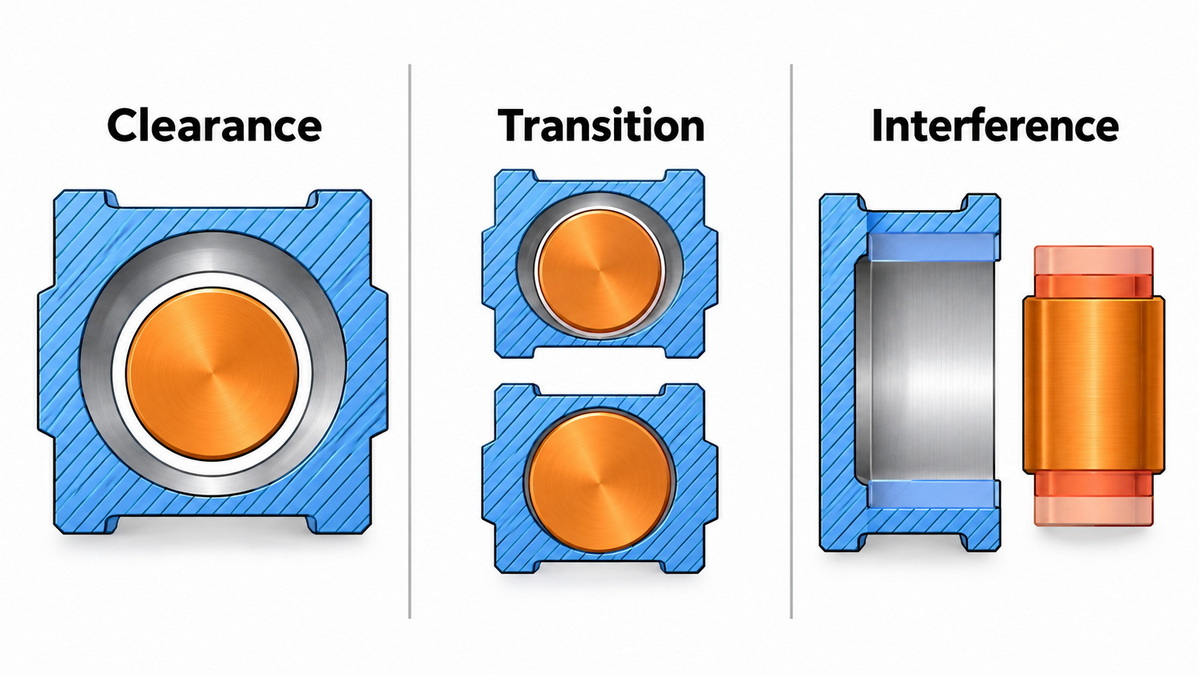
A clearance fit places the shaft tolerance zone below the hole tolerance zone, providing clearance across the specified mating limits.
This type of fit is commonly associated with sliding, rotating, or removable components.
The engineering challenge is balancing two requirements:
- Minimum clearance must support the intended assembly and movement.
- Maximum clearance must remain compatible with acceptable play and alignment.
Selecting a clearance-fit designation is only the beginning. The resulting dimensional limits must suit the application.
A transition fit can produce either clearance or interference, depending on the actual dimensions of the mating parts.
This relationship can support close location, but assembly behavior varies within the specified limits.
A transition fit should therefore not be described as guaranteed hand assembly or guaranteed press assembly. Engineers must determine whether the assembly process can accommodate both possible outcomes.
An interference fit makes the shaft larger than the mating hole across the specified limits.
Assembly may involve pressing or controlled thermal methods. However, the dimensional overlap alone does not fully define joint performance.
Before approving the design, review the intended loading, material combination, engagement geometry, and assembly method. The fit specification must support the complete joint requirement, not merely produce dimensional overlap.
Consider an illustrative shaft-and-hole design:
| Feature | Minimum size | Maximum size |
|---|---|---|
| Hole | 20.000 mm | 20.020 mm |
| Shaft | 19.990 mm | 20.000 mm |
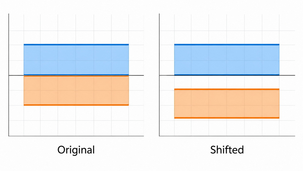
The design permits zero clearance at its limiting combination. If the mechanism requires positive minimum clearance, these limits do not guarantee it.
Now change the shaft limits to 19.985–19.995 mm while leaving the hole unchanged.
The resulting clearance range becomes 0.005–0.035 mm. The shaft tolerance width remains 0.010 mm.
The fit changed because the shaft tolerance zone moved—not because the shaft became more tightly toleranced.
This example illustrates an important distinction: engineers must consider both tolerance width and tolerance-zone position. Whether the revised clearance range is suitable remains an application-specific decision.
Start with a clear functional statement:
- The shaft must slide without binding.
- The locating interface must maintain repeatable alignment.
- The retained joint must withstand its intended loading.
- The component must be removable during maintenance.
Translate that statement into measurable requirements. "A close fit" is less useful than a defined allowable clearance range.
Separate functional interfaces from noncritical surfaces.
A locating bore may require close dimensional and geometric control. An external surface may not need the same precision.
This distinction allows the drawing to concentrate manufacturing effort where variation would affect performance.
An ISO fit designation combines a letter with a tolerance grade.
Uppercase letters identify hole tolerance classes; lowercase letters identify shaft classes. The letter establishes the tolerance zone's position relative to nominal size, while the grade establishes its width.
Confirm the numerical limits for the selected nominal size. A designation should not replace a review of minimum and maximum clearance or interference.
Size limits do not fully define assembly geometry.
Depending on the interface, engineers may also need controls for:
- Position.
- Orientation.
- Form.
- Runout.
- Relationships to datum features.
For example, an acceptable bore diameter does not automatically establish correct alignment with another feature.
Use a consistent drawing standard and ensure that the supplier understands the intended datum structure.
Discuss how each critical feature will be produced and when its final dimensions will be established.
A demanding tolerance may require additional machining, finishing, or inspection. That does not make the requirement wrong, but it should have a functional justification.
The useful distinction is between a requirement that is difficult to manufacture and one that is unnecessary.
Before production, define the inspection approach for critical features.
Discuss measurement conditions, applicable geometric requirements, sampling expectations, and acceptance criteria.
This prevents different interpretations of "precision" from entering the quotation and production process.
Dimensional measurements use 20°C as their reference temperature. Measurements at other temperatures may require appropriate correction.
For critical interfaces, review:
- The specified reference temperature.
- Whether components stabilize before inspection.
- Differences between mating materials.
- The intended operating temperature range.
A room-temperature clearance calculation should not automatically be treated as proof of performance under every service condition.
Instrument resolution and measurement uncertainty are different concepts.
A display showing many decimal places does not, by itself, establish that a measurement is suitable for accepting a tightly toleranced feature.
Ask how the complete inspection method supports the specification. Temperature, measurement technique, and other uncertainty contributors matter alongside the instrument's displayed resolution.
One conforming prototype proves that one component met its requirements. It does not establish production consistency.
Process capability compares the performance of a stable process with its specification limits. Capability indices can help evaluate process spread and centering.
For repeat production, discuss:
1. Which features require capability evaluation.
2. How samples will be collected.
3. How process stability will be assessed.
4. What action follows a process change.
Capability expectations should reflect the application and customer requirements rather than an unexplained universal threshold.
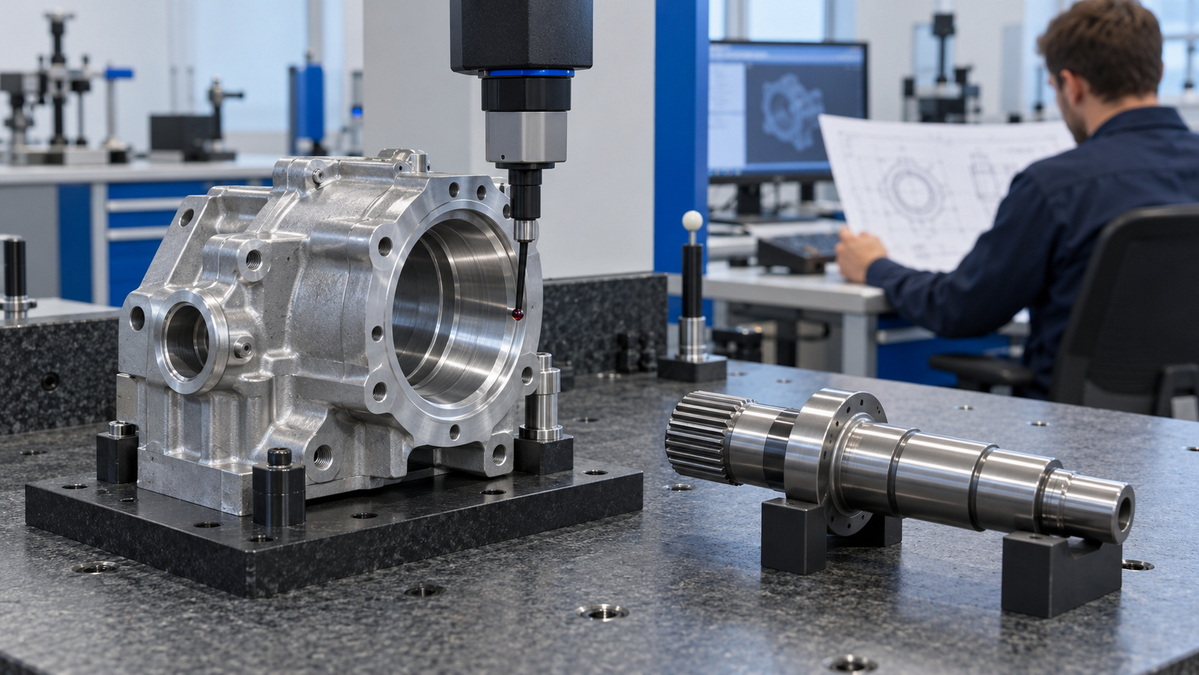
U-Need supports global brands, distributors, and manufacturers through custom precision parts machining, mold manufacturing, and sheet metal fabrication in China.
A function-first drawing review can organize requirements across these services without assuming identical tolerancing capability for every process.
Identify mating diameters, locating features, and the geometric relationships that govern assembly.
Provide information about the mating component whenever possible. Reviewing one part in isolation can hide the combined dimensional requirement.
For injection molds, stamping dies, and cold-forging dies, identify interfaces that locate, guide, or retain tooling components.
Explain the intended relationship between mating features rather than relying on a general request for high precision.
For laser-cut, bent, and stamped components, distinguish individual dimensions from assembly-level relationships.
Identify which features govern alignment, attachment, or mating behavior after forming and assembly. The review should address the completed functional condition.
Before requesting a quotation, ask:
- What must each mating interface do?
- What minimum and maximum clearance or interference are acceptable?
- Are both mating components adequately specified?
- Are the fit designation and numerical limits consistent?
- Are datums and geometric controls sufficient?
- Have temperature and measurement uncertainty been considered?
- Does the manufacturing plan support repeat production?
- Which tolerances can be relaxed without changing performance?
This checklist connects design intent with manufacturing feasibility and verification.
Tight tolerance machining and fit requirements perform different but complementary roles.
Fit requirements establish how mating components must interact. Dimensional and geometric tolerances define the permitted variation. Manufacturing and inspection then determine whether those requirements can be achieved consistently.
The strongest specification does not demand maximum precision everywhere. It identifies critical interfaces, checks limiting combinations, and applies the control necessary for reliable performance.
Send U-Need your 2D drawings, 3D models, materials, expected quantities, and a description of the intended assembly behavior.
Highlight the features controlling movement, alignment, retention, or serviceability. Request a feature-specific discussion covering dimensional limits, geometric requirements, manufacturing sequence, and inspection expectations.
This creates a clearer basis for quotation and helps align the production plan with the requirements that matter.
No. Tighter limits are valuable when they protect a functional requirement. Unnecessarily demanding tolerances can introduce additional operations without improving assembly performance.
Tolerance defines allowable variation in an individual feature. Fit describes the dimensional relationship between mating features, including possible clearance or interference.
Yes. Both components can meet their individual limits while their combined dimensions fail to support the intended assembly behavior. Check the limiting mating combinations during design.
No. H7 specifies the hole tolerance class. The mating shaft's tolerance zone determines the resulting relationship between the components.
No. Size limits and geometric controls address different requirements. A diameter limit alone does not fully describe feature location, orientation, or relationships to other features.
Review the inspection method, process stability, and capability evidence for selected critical features. Do not infer consistent production performance from a single conforming sample.
The worked dimensional example is illustrative and is not presented as a verified customer project. U-Need's service descriptions are based on the company background supplied for this article. The technical discussion draws on the following publications and resources:
1. Department of Standards Malaysia — Preview of ISO 286-1:2010, "Geometrical Product Specifications—ISO Code System for Tolerances on Linear Sizes." Supports the explanation of tolerance systems, deviations, and fits. [mysol.jsm.gov]
2. ASME — "Dimensioning and Tolerancing." Supports the discussion of geometric controls, datum references, and drawing interpretation. [asme]
3. Protolabs — "Understanding CNC Machining Tolerances." Supports the relationship between stringent tolerances, manufacturing operations, cost, and lead time. [protolabs]
4. Protolabs Network — "CNC Machining ISO-Based Tolerances and Finishes." Supports feature-specific tolerancing and manufacturability considerations. [hubs]
5. NIST — "Uncertainties in Dimensional Measurements Made at Nonstandard Temperatures." Supports the discussion of temperature effects and dimensional measurement uncertainty. [nvlpubs.nist]
6. NIST — "Measurement Uncertainty." Supports the distinction between dimensional tolerances and measurement uncertainty. [nvlpubs.nist]
7. NIST/SEMATECH Engineering Statistics Handbook — "What Is Process Capability?" Supports the explanation of process stability, specification limits, and capability indices. [itl.nist]
8. Xometry Pro — "Limits & Fits Calculator—ISO 286 Tolerances." Provides a practical resource for examining shaft-and-hole limits and resulting fit relationships. [xometry]


