Views: 218 Author: U-Need Publish Time: 2026-10-22 Origin: Site
Content Menu
● What Is Built-Up Edge in CNC Machining?
>> Built-Up Edge Versus Built-Up Layer
● What Causes Built-Up Edge During Machining?
>> Adhesive Workpiece Materials
>> Cutting Speed Below the Appropriate Range
>> Unsuitable Geometry and Ineffective Lubrication
● How Built-Up Edge Affects Precision Part Quality
● How to Diagnose Built-Up Edge Without Guesswork
● How to Prevent Built-Up Edge: A Controlled Workflow
>> 1. Establish a Repeatable Baseline
>> 2. Match the Tool to the Material
>> 3. Adjust Cutting Speed Within Supported Limits
>> 4. Review Feed and Engagement
>> 5. Improve Coolant Delivery and Chip Removal
>> 6. Validate More Than One Good Part
● A Practical Example: Aluminum Pocket Finishing
● Can Built-Up Edge Ever Protect a Cutting Tool?
● What Buyers Should Ask a Precision Machining Supplier
● Discuss Your Precision Manufacturing Project with U-Need
>> What is the main cause of built-up edge?
>> Should I increase or decrease cutting speed to reduce BUE?
>> Is built-up edge the same as tool wear?
>> Does more coolant always prevent built-up edge?
>> Which materials commonly develop built-up edge?
>> How can I confirm that a corrective action worked?
Built-up edge in CNC machining can turn a sharp cutting tool into an unpredictable cutting surface. Workpiece material adheres to the edge, changes its geometry, and repeatedly breaks away. The result may be a rough finish, inconsistent dimensions, and unexpected tool damage.
For buyers sourcing precision parts, the concern is not simply whether a supplier recognizes this defect. It is whether the supplier can identify the cause, validate a corrective action, and maintain consistent quality throughout production.
This guide explains how built-up edge forms, how to distinguish it from other machining problems, and how to control it through tooling, cutting parameters, lubrication, and inspection.
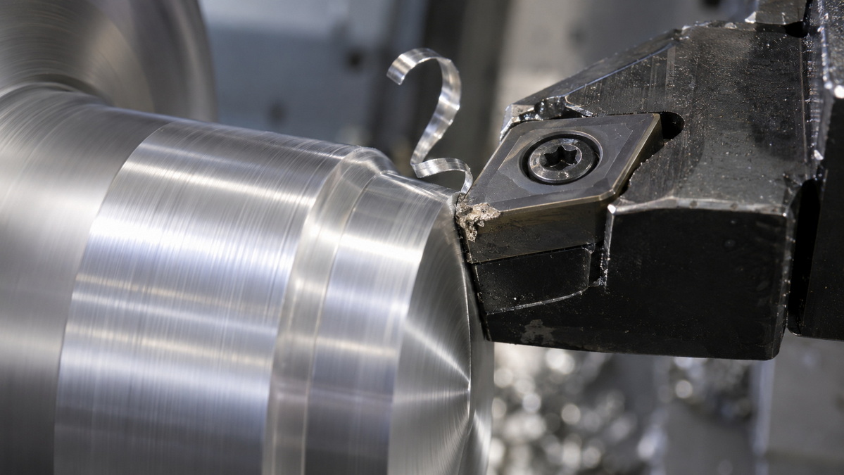
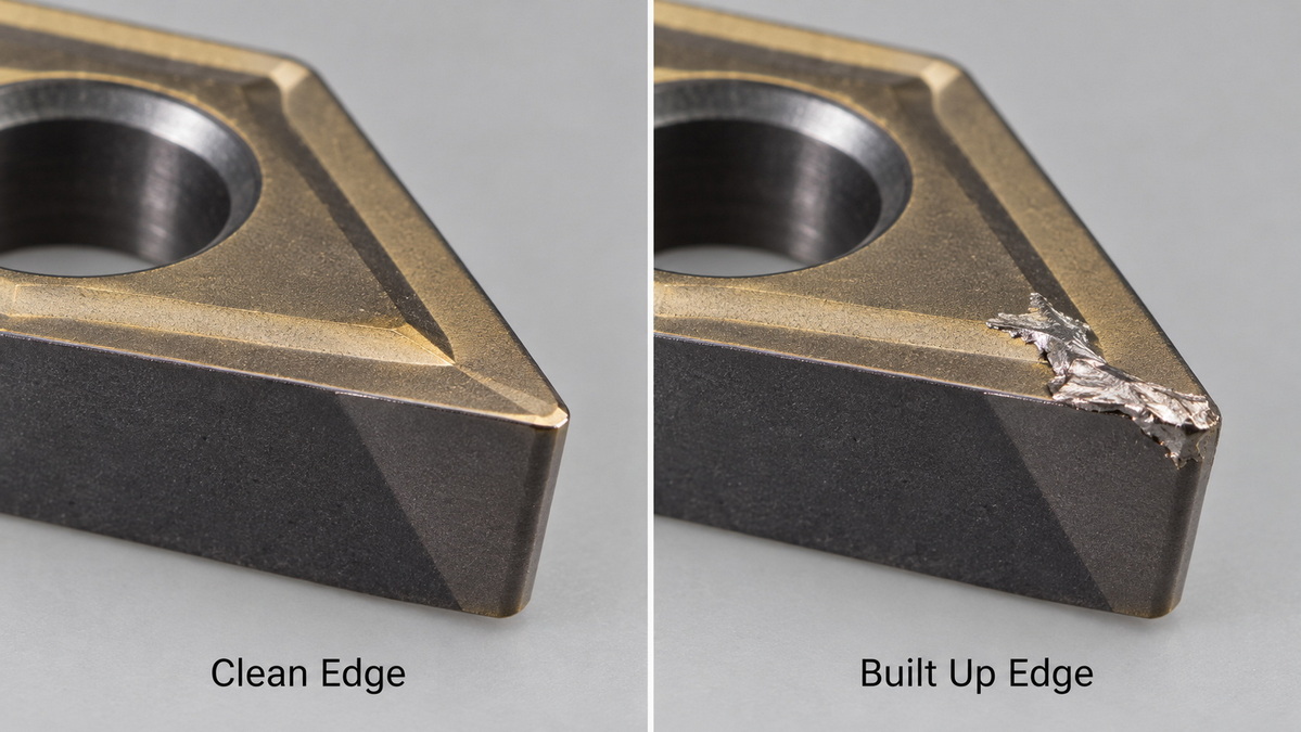
Built-up edge, usually abbreviated as BUE, is an accumulation of workpiece material attached to a cutting edge. It develops through adhesion and pressure welding at the contact between the chip and tool.
Unlike a deliberately applied tool coating, BUE is an uncontrolled deposit. It can grow, change shape, and detach during cutting. Fragments may leave with the chip, damage the edge, or become embedded in the machined surface.
The practical distinction matters: a cutter can appear to be cutting with its original geometry while actually cutting with an unstable deposit attached to it.
A built-up layer describes adhered material spread over a tool surface, commonly the rake face. Built-up edge specifically changes the active cutting edge. They can coexist, but their position and influence differ.
For troubleshooting, inspect where the material accumulates rather than labeling every deposit as the same failure. The diagnosis should connect the deposit to the observed surface or dimensional problem.
BUE usually reflects an interaction between material adhesion, cutting speed, edge condition, and lubrication. Treating it as a temperature problem alone can lead to the wrong adjustment.
Aluminum, low-carbon steel, and stainless steel are common candidates. Their tendency to adhere means that tool geometry and cutting conditions deserve particular attention.
However, a material name alone cannot determine the correct setup. Alloy composition, condition, and the specific operation influence tool selection. A successful aluminum milling strategy should not automatically become the standard for stainless steel turning.
Low cutting speed can encourage BUE. This is an important correction to the assumption that slower cutting always protects the tool.
Increasing cutting speed within the tool manufacturer's recommended range may reduce adhesion. Increasing it without limits can create other problems, including faster flank wear, crater wear, or plastic deformation.
The goal is a suitable operating window, not the highest possible spindle speed.
An edge that rubs instead of cutting efficiently can aggravate adhesion. Dull tools, unsuitable edge preparations, and geometry poorly matched to the material deserve investigation.
Lubrication also matters. Coolant should reach the cutting zone, and its concentration should follow the fluid manufacturer's instructions. A full coolant tank does not demonstrate effective delivery at the tool–chip interface.
BUE changes the effective edge geometry. As the deposit grows and detaches, cutting conditions can change even when the programmed parameters remain constant.
Potential consequences include:
- Smeared material, tearing, and an inconsistent surface appearance.
- Variation in dimensions between successive parts.
- Irregular cutting forces and less predictable tool performance.
- Edge damage when adhered material breaks away.
- Additional inspection, rework, or rejected components.
Surface appearance is only one part of the assessment. A feature can look acceptable while dimensions drift, or measure correctly while its surface fails the specified finish requirement.
A production decision should therefore consider the drawing's dimensional and surface requirements together.
My recommended starting point is to inspect the cutting edge before changing the program. Similar surface defects can have different causes, so an adjustment based only on appearance may waste tools and parts.
Stop the machine safely and follow the site's inspection procedure. Examine the tool under suitable magnification, then compare the findings with the latest parts and process records.
| Observation | Possible explanation | Useful next check |
|---|---|---|
| Workpiece-colored material attached to the edge | Adhesion consistent with BUE | Inspect the deposit and edge condition |
| Regular waves on the surface | Chatter or vibration | Check workholding, tool projection, and stability |
| A worn band along the clearance face | Flank wear | Compare with the tool supplier's wear guidance |
| Scratches associated with trapped chips | Chip recutting or poor evacuation | Check chip removal and coolant direction |
| Intermittent smearing with changing dimensions | Possible unstable BUE | Correlate edge images with sequential measurements |
This table is a diagnostic aid, not proof. Several problems can occur simultaneously. Visible adhesion may coexist with chatter, worn tooling, or inadequate chip evacuation.
Record the material designation, tool identification, operation, cutting speed, feed, depth of cut, coolant condition, and toolholder arrangement.
Keep representative parts and tool images where practical. Record measurements at consistent points so that later comparisons reflect actual process changes rather than different inspection methods.
Without a baseline, an apparent improvement can be difficult to reproduce.
Choose geometry, edge preparation, and coating for the specific alloy and operation. Do not assume that a harder coating automatically prevents adhesion.
For aluminum applications, polished cutting surfaces and suitable nonferrous geometries are established options. Seco describes polished features and application-specific coatings designed to reduce BUE in aluminum machining.
Use the tool supplier's application guidance as the starting point. Then validate the choice against the component's geometry, finish, and tolerance requirements.
If inspection confirms BUE and cutting speed is low for the application, evaluate a controlled increase within the recommended range.
Keep other variables constant where practical. Check both the surface and the tool afterward. Reduced adhesion is not a complete success if the adjustment introduces rapid wear or unacceptable dimensional variation.
Avoid reducing feed automatically whenever the surface becomes rough. An excessively light cut can produce rubbing rather than effective chip formation.
Review the tool supplier's recommended feed and account for engagement, especially in milling. The appropriate adjustment depends on whether the operation involves a turning insert, an end mill, or another tool.
Change one factor at a time when feasible, and document the effect.
Check nozzle direction, access to the cutting zone, fluid condition, and concentration. Follow the coolant manufacturer's guidance rather than adding concentrate by guesswork.
Remove chips effectively so they do not repeatedly enter the cutting zone. Through-tool coolant may help where access and chip evacuation are difficult, but it is not a universal substitute for suitable geometry and parameters.
Coolant strategy must also suit the tool material and operation. Some tooling applications have different recommendations, particularly where thermal cracking is a concern.
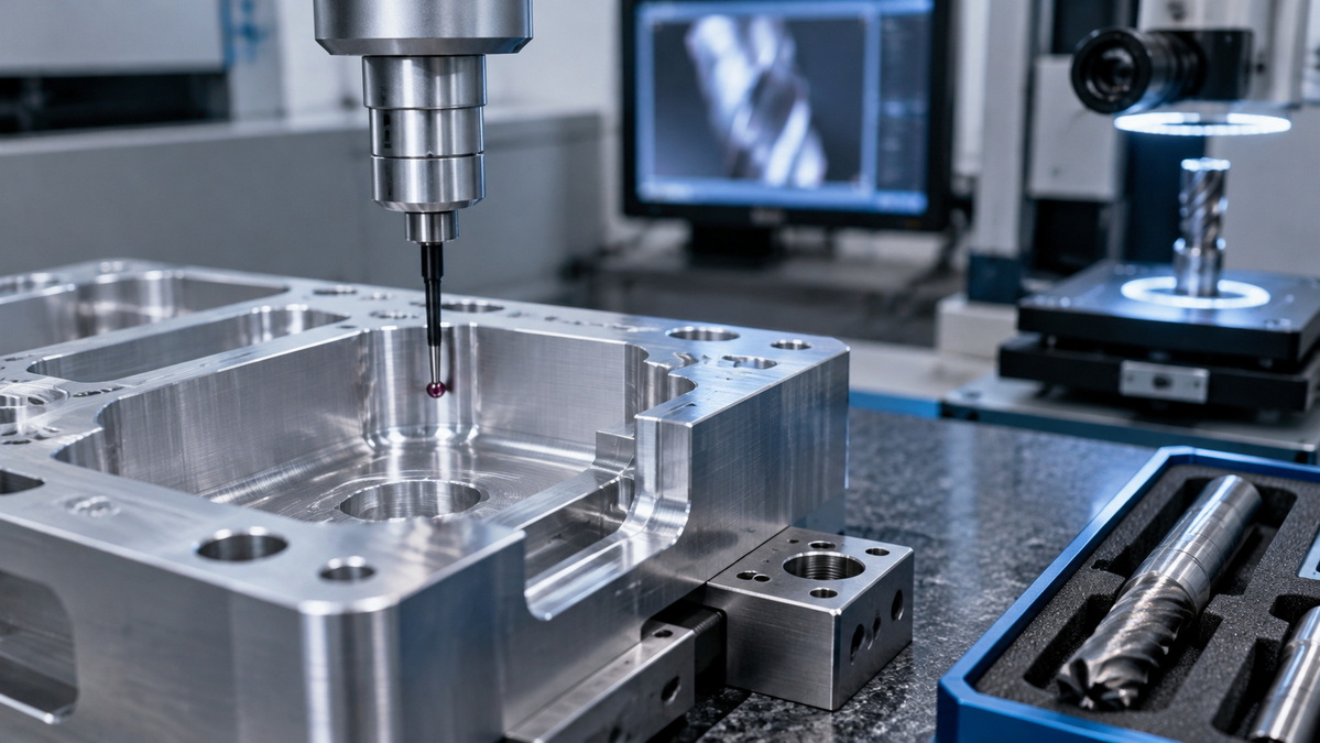
Inspect consecutive parts and examine the tool after a representative cutting interval. A single acceptable component does not establish a stable process.
Confirm dimensional consistency, finish compliance, and acceptable edge condition. Record the approved settings so that another operator can repeat the process without relying on memory.
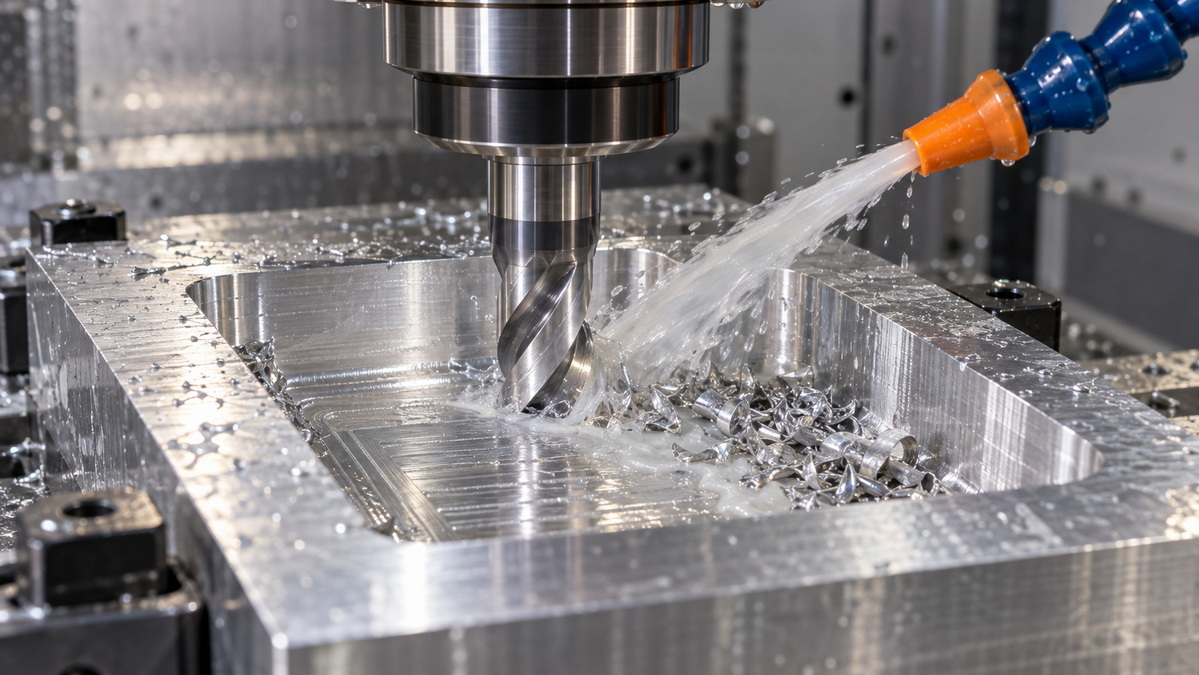
Consider an illustrative case, not a reported customer result: an aluminum pocket shows intermittent smearing after finishing, and inspection reveals adhered material on the end mill.
The first response should not be an arbitrary reduction in spindle speed. Instead, verify the cutter's suitability for aluminum, the actual cutting speed, coolant access inside the pocket, and chip evacuation.
A controlled trial could proceed as follows:
1. Install a suitable fresh tool and document the starting condition.
2. Restore coolant concentration and delivery to the recommended condition.
3. Test a supported cutting-speed adjustment while keeping other settings unchanged.
4. Measure consecutive pockets and inspect the cutting edge.
5. Retain the change only if both part quality and tool condition improve.
This example illustrates a decision process, not a guaranteed recipe. Without the alloy, diameter, tool specification, and machine limits, prescribing a universal speed or feed would be unreliable.
Adhered material can sometimes separate the underlying tool from direct contact with the workpiece. That observation does not make uncontrolled BUE a dependable production strategy.
For precision work, an unstable deposit changes the effective cutting geometry and can compromise consistency. Any claimed protective effect needs to be evaluated for the specific process, rather than presented as a general improvement in finish or tool life.
The practical objective is predictable cutting behavior, not simply the presence or absence of material on the tool.
A useful supplier discussion goes beyond asking whether the shop can achieve a nominal tolerance. Ask how it controls variation during the production run.
Relevant questions include:
- How are tools selected for the specified alloy and operation?
- What inspection method verifies critical dimensions and surface finish?
- How are tool changes and process adjustments recorded?
- What happens when measurements begin to drift?
- How are approved conditions transferred from sampling to production?
These questions help connect machining expertise to repeatable delivery. For a quotation, provide the drawing, material specification, quantities, critical features, and surface requirements.
U-Need supports global brands, distributors, and manufacturers with custom precision parts machining, mold manufacturing, and sheet metal fabrication in China.
Its stated service scope includes injection molds, stamping dies, cold-forging dies, laser cutting, bending, and stamping.
Send U-Need your drawings and project requirements to request a manufacturing review and quotation. Include the material, tolerances, finish requirements, quantities, and any existing defect photographs. These details support a more specific discussion of manufacturability and process control.
BUE forms when workpiece material adheres or pressure-welds to the cutting edge. Adhesive materials, low cutting speed, unsuitable tooling, and ineffective lubrication can contribute.
A controlled increase can help when speed is too low. Stay within application recommendations and monitor wear, finish, and dimensions. There is no universal setting.
No. BUE is adhered workpiece material. Tool wear involves deterioration of the tool itself, although adhesion and detachment can contribute to damage.
No. Correct fluid selection, concentration, and delivery matter more than volume alone. Coolant cannot compensate for every tooling or parameter problem.
Aluminum, low-carbon steel, and stainless steel are common examples. Actual behavior depends on the alloy, tool, and cutting conditions.
Compare tool condition, surface finish, and measurements across consecutive parts. Accept the adjustment only when it improves repeatability without introducing another failure mode.
1. TOPS — "Causes & Effects of Build Up Edge (BUE) In CNC Machining." [topsbest-precision]
2. Sandvik Coromant — "Wear on Cutting Edges." [sandvik.coromant]
3. Sandvik Coromant — "How to Improve Tool Life in Turning."[sandvik.coromant]
4. Seco Tools — "4 Tips for Next Level Performance in Aluminum Machining." [secotools]
5. Sandvik Coromant — "Cutting Tool Materials: Advantages & Recommendations for Best Use." [sandvik.coromant]
6. Haas Automation — "TSC = Peace of Mind — Mark Talks Through-Spindle Coolant"及"Chip & Coolant Management for Machine Tools." [haascnc]


