Views: 234 Author: U-Need Publish Time: 2026-09-06 Origin: Site
Content Menu
● What Is Tight Tolerance Machining?
● What Is Standard CNC Machining?
● Tight Tolerance Machining vs Standard CNC Machining
● Why Tighter Tolerances Are Not Always Better
>> Common Cost Drivers of Tight Tolerance Machining
● When Do Engineers Need Tight Tolerance Machining?
>> Precision Fits and Assembly Interfaces
>> Sealing and Fluid-Control Components
>> Motion and Automation Systems
>> Molds, Dies, and Tooling Components
● When Is Standard CNC Machining the Better Choice?
>> Standard Tolerances Still Need Clear Drawings
● How to Choose the Right Tolerance for Each Feature
>> 1. Identify Functional Features
>> 2. Define the Assembly Relationship
>> 4. Consider Tolerance Stack-Up
>> 5. Confirm Inspection Before Production
● Why Inspection Is Essential for Tight Tolerance Parts
● Material and Geometry Can Change Tolerance Capability
● Secondary Processes Must Be Included in Tolerance Planning
● How U-Need Supports Better Manufacturing Decisions
>> 1. What is considered a tight tolerance in CNC machining?
>> 2. Can CNC machining achieve ±0.01 mm tolerance?
>> 3. Why does tight tolerance machining cost more?
>> 4. Should every feature on a precision part use a tight tolerance?
>> 5. What is the difference between dimensional tolerance and geometric tolerance?
>> 6. How do I choose between standard and tight tolerances?
>> 7. Can sheet-metal fabrication hold tight tolerances?
Engineers do not need the tightest tolerance on every dimension. They need the right tolerance for the part's real function.
The choice between tight tolerance machining and standard CNC machining affects part performance, assembly fit, inspection methods, production lead time, and total manufacturing cost. A dimension that is unnecessarily strict can raise the price of a component without improving its reliability. A dimension that is too loose can cause misalignment, leakage, vibration, poor fit, or premature wear.
For global brands, distributors, and manufacturers, the most effective approach is to identify the features that truly control product performance. Those features deserve precise control. Other dimensions should use practical general tolerances that support efficient, repeatable production.
U-Need provides custom precision parts machining, mold manufacturing, sheet metal fabrication, laser cutting, bending, stamping, and related production support. This article helps engineers make more informed tolerance decisions before requesting quotations, producing prototypes, or releasing parts for volume manufacturing.
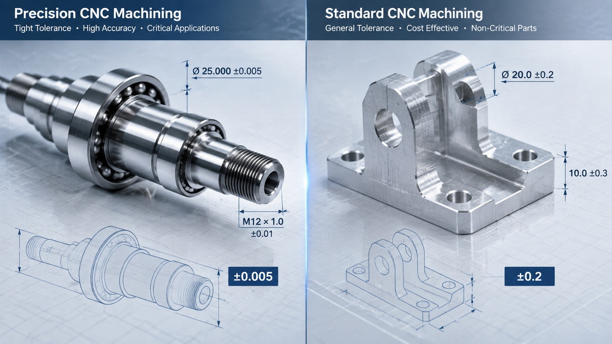
Tight tolerance machining is a precision manufacturing process used to control dimensions, geometry, and surface conditions within a narrow allowable range.
A tolerance defines how much a finished dimension may vary from its nominal target value. For example, a hole specified as 20.00 mm ±0.05 mm can measure from 19.95 mm to 20.05 mm and still meet the drawing requirement.
A tighter tolerance reduces that allowable range.
For example:
- A feature specified as 20.00 mm ±0.10 mm has a total tolerance range of 0.20 mm.
- A feature specified as 20.00 mm ±0.01 mm has a total tolerance range of only 0.02 mm.
- The second requirement gives the manufacturer far less room for variation.
Tight tolerance machining may involve precision CNC milling, CNC turning, grinding, reaming, honing, lapping, wire EDM, or other controlled finishing methods. The correct process depends on the material, part geometry, surface requirement, production quantity, and functional purpose of the feature.
In many projects, tight tolerance machining is needed for only a small number of dimensions. These may include a locating bore, a bearing seat, a precision shaft, a sealing face, a mating flange, or a hole pattern that must align accurately with another assembly.
Standard CNC machining refers to the production of components using practical tolerances suitable for general mechanical function and cost-efficient manufacturing.
It does not mean low quality or uncontrolled production. It means the manufacturer applies normal machining capability, process control, and inspection methods without adding unnecessary high-precision operations to every feature.
Standard CNC machining is commonly used for:
- Equipment brackets
- Mounting plates
- General housings
- Structural supports
- Protective covers
- Enclosures
- Machine guards
- Spacers
- Non-critical shafts
- Sheet-metal parts
- Cosmetic components
Many suppliers use a standard machining tolerance around ±0.05 mm to ±0.13 mm for general CNC features, depending on the process, material, feature size, and drawing requirements. Features with no individual tolerance may also be governed by a general tolerance standard specified on the drawing.
The key point is simple: standard tolerances can deliver excellent quality when they match the functional needs of the part.
The following comparison shows how the two approaches differ in practical engineering and manufacturing situations.
| Comparison Factor | Tight Tolerance Machining | Standard CNC Machining |
|---|---|---|
| Main purpose | Control critical dimensions and geometry | Produce reliable parts efficiently |
| Typical tolerance level | Often ±0.025 mm, ±0.01 mm, or tighter on selected features | Often ±0.05 mm to ±0.13 mm for general features |
| Suitable applications | Bearing fits, locating bores, sealing surfaces, motion systems | Brackets, frames, housings, covers, support components |
| Setup requirements | Advanced fixturing and datum control | Conventional workholding methods |
| Machining process | May require finishing passes, reaming, grinding, or honing | Usually relies on standard milling or turning operations |
| Inspection method | CMM, bore gauges, air gauges, precision gauges, detailed reports | Calipers, micrometers, gauges, sample inspection |
| Production cost | Higher due to machining and inspection effort | More economical for non-critical features |
| Manufacturing risk | Higher if design requirements are unclear | Lower when tolerances are practical |
| Lead time | May increase because of setup and verification | Often faster for standard production |
| Best engineering strategy | Apply only where function requires it | Use for dimensions with sufficient design margin |
The best drawing often uses both approaches. It applies tight tolerances to the dimensions that control performance and practical tolerances to the remaining features.
A tight tolerance may look like a higher-quality requirement, but it can create avoidable cost and manufacturing difficulty.
Each reduction in the allowable tolerance range can require additional resources. The manufacturer may need slower cutting speeds, more stable fixturing, more frequent tool changes, extra finishing operations, and longer inspection time.
Tighter requirements can also increase the chance of part rejection. A part may be fully functional in the final assembly but still fail inspection because a non-critical dimension falls slightly outside an unnecessarily narrow drawing limit.
The following factors often increase when a drawing includes many tight tolerances:
- More complex fixtures to control part movement and preserve datum relationships
- Additional setups to machine features accurately from multiple directions
- Slower finishing operations to reduce dimensional variation
- Higher tool management requirements to control wear
- Specialized equipment such as precision reamers, grinding machines, or coordinate measuring machines
- More in-process inspection to verify dimensions before the part leaves the machine
- Longer quality documentation time for critical characteristics
- Higher scrap risk when a small variation causes a part to fall outside the specified range
- Longer lead times for first article approval and production validation
For this reason, engineers should avoid applying tight tolerances to every surface or dimension. A tolerance should solve a functional problem, not create a theoretical level of precision that the product does not need.
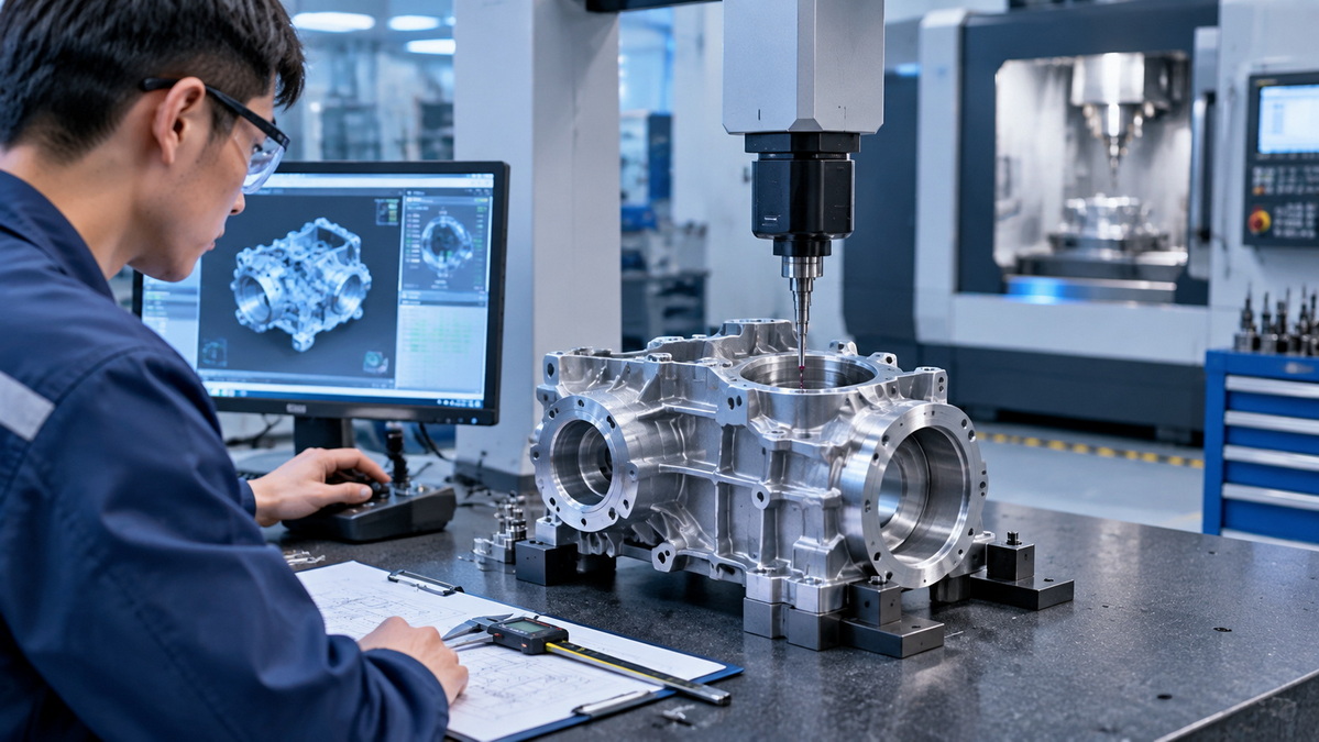
Tight tolerance machining is appropriate when a small variation could directly affect fit, function, safety, movement, sealing, or product quality.
Tight tolerances are often necessary when one component must fit another component with a controlled relationship.
Typical examples include:
- Shafts and bearings
- Bushings and housings
- Press-fit pins
- Dowel holes
- Gear mounting features
- Precision guide rails
- Motor mounting bores
- Tooling inserts
- Injection mold components
- Cold-forging die components
A shaft that is too large may not enter a bearing or bore. A shaft that is too small may create unwanted play, vibration, noise, or wear.
Hydraulic, pneumatic, vacuum, and fluid-handling parts often require tight control because small deviations can cause leakage or pressure loss.
Critical features may include:
- Valve seats
- O-ring grooves
- Threaded sealing interfaces
- Pump housings
- Internal fluid passages
- Mating flanges
- Flat sealing faces
- Concentric bore-and-shaft features
For these parts, size alone may not be enough. Engineers may also need to define flatness, roundness, cylindricity, concentricity, surface finish, and positional relationships.
Precision motion systems can magnify small dimensional errors. A minor location error may cause binding, increased friction, poor repeatability, vibration, or accelerated component wear.
Tight tolerance machining is often valuable for:
- Robotic end-effectors
- Linear-motion assemblies
- Servo motor housings
- Precision fixture plates
- Automation tooling
- Sensor mounts
- Camera housings
- Optical mounts
- High-speed rotating components
- Semiconductor equipment components
In these situations, the relationship between features can be more important than the tolerance of an isolated dimension.
Mold manufacturing and die manufacturing frequently involve close-fitting features that must work together repeatedly under load, heat, and production cycles.
Examples include:
- Mold inserts
- Core and cavity components
- Guide pillars
- Ejector pin holes
- Slide components
- Punches
- Die plates
- Forming tools
- Alignment features
For these parts, a small dimensional variation can affect flash, parting-line quality, repeatability, tool life, wear, and maintenance frequency.
Standard CNC machining is usually the better choice when the part has enough functional clearance and a small dimensional difference will not affect assembly or performance.
Common applications include:
- Machine frames
- Equipment panels
- Protective guards
- Covers and lids
- General mounting brackets
- Base plates
- Storage and transport fixtures
- Non-critical spacer blocks
- Cabinet components
- Sheet-metal enclosures
- General structural parts
For example, a mounting bracket may need its bolt-hole pattern located accurately enough to install onto a frame. However, the outside edge of the bracket may not need the same strict control if it does not touch another component or affect the product's appearance.
Using a standard tolerance for that outside profile can reduce machining cost while maintaining the required function.
Practical tolerances do not replace good engineering communication. A complete manufacturing drawing should still include the information needed to produce and inspect the part consistently.
Important drawing details include:
- Nominal dimensions
- Material grade
- Surface finish requirements
- Critical dimensions
- Datum references
- Thread specifications
- Deburring requirements
- Edge-break requirements
- Surface treatment requirements
- Heat-treatment requirements
- General tolerance notes
- Revision control information
A clear drawing helps the supplier distinguish between features that must be tightly controlled and features that can follow general manufacturing tolerance rules.
Engineers should not begin by asking, "What is the tightest tolerance this supplier can hold?"
A better question is: "What amount of variation can this feature allow while the product still performs correctly?"
Use the following process to make a more practical tolerance decision.
Start by identifying every feature that influences product function.
These can include:
- Mating surfaces
- Mounting holes
- Bearing seats
- Sealing grooves
- Press-fit interfaces
- Threaded connections
- Moving surfaces
- Alignment features
- Cosmetic gaps
- Electrical connector openings
Not every dimension has the same importance. A critical bore may control the entire assembly, while an external corner may have little or no functional effect.
Consider how the part works with other components.
Ask:
- Does the feature locate another component?
- Does it need clearance for assembly?
- Does it require interference for a press fit?
- Does it influence movement or rotation?
- Does it create a seal?
- Does it affect visual alignment?
- Does it experience heat, vibration, or repeated loading?
The answers help determine whether a dimension should receive a tight tolerance, a moderate tolerance, or a general tolerance.
Datums establish the references used for manufacturing and inspection.
A strong datum strategy reflects how the part is actually mounted, assembled, and measured. It helps control the relationship between critical features instead of treating every dimension independently.
For example, a housing may use:
- The mounting face as the primary datum
- A side face as the secondary datum
- A locating hole or edge as the tertiary datum
This approach can help ensure that a precision bore is correctly positioned relative to the mounting face and other assembly features.
A tolerance stack-up occurs when variation from several parts or features combines in one assembly.
For example, a connector may pass through:
- A housing opening
- A gasket
- A mounting plate
- A cable bracket
- A mating connector
Each feature may have its own allowable variation. If all dimensions shift in the same direction, the final assembly may not fit even though every individual component is within its specified tolerance.
Tolerance stack-up analysis helps engineers identify where precision matters most.
A tolerance is only useful if it can be measured reliably.
Before finalizing a critical requirement, confirm:
- The planned measurement instrument
- The measurement range
- The expected measurement accuracy
- The inspection fixture or setup
- The location of measurement points
- The required inspection frequency
- The report format
- The environmental conditions during inspection
For simple features, calipers or micrometers may be enough. For complex geometries, a coordinate measuring machine, optical measuring system, bore gauge, plug gauge, thread gauge, or custom inspection fixture may be necessary.

Tight tolerance machining is not only a machining challenge. It is also a measurement challenge.
A supplier must be able to verify the dimension with an inspection method that is more precise than the allowable tolerance range. If the measurement uncertainty is too large, the inspection result may not provide a dependable pass-or-fail decision.
Different part features require different inspection tools.
| Feature Type | Common Inspection Method |
|---|---|
| External diameter | Micrometer, laser micrometer, optical system |
| Internal bore | Bore gauge, plug gauge, air gauge, CMM |
| Thread | Go/no-go gauge, thread micrometer, optical inspection |
| Hole location | CMM, vision measuring system, fixture gauge |
| Flatness | Surface plate, height gauge, CMM |
| Surface roughness | Surface roughness tester |
| Complex profile | CMM, optical measurement system, custom gauge |
| Sheet-metal bend angle | Angle gauge, fixture gauge, CMM, optical system |
For critical production parts, inspection may take place at several stages:
1. Incoming material verification
2. First-piece inspection
3. In-process measurement
4. Final inspection
5. Outgoing quality documentation
This layered approach helps reduce the risk of producing a full batch with an undetected dimensional issue.
The same tolerance requirement can be easy for one part and difficult for another.
Material behavior, part geometry, wall thickness, clamping force, tool access, machining sequence, and secondary processes all affect the final result.
Different materials react differently during machining.
- Aluminum is generally efficient to machine, but thin-wall features can distort after material removal.
- Stainless steel can generate more heat and may require careful tool selection and cutting parameters.
- Titanium can create heat-management and tool-wear challenges.
- Copper alloys may form burrs and can require attention when machining fine features.
- Engineering plastics may deform under clamping pressure or change dimensionally with temperature and moisture.
- Hardened steel may require grinding or EDM for fine details and strict accuracy.
Engineers should pay special attention to:
- Long, thin walls
- Deep pockets
- Deep bores
- Small internal radii
- High aspect-ratio features
- Complex internal cavities
- Thin ribs
- Multi-axis features
- Features machined in different setups
- Tight relationships between distant surfaces
A ±0.01 mm tolerance on a short external diameter may be manageable. The same tolerance on a deep internal bore, positioned relative to a face machined in a separate setup, may require a far more controlled process.
Machining may not be the final manufacturing step. Surface finishing and downstream processes can affect dimensions, surface condition, and fit.
Engineers should define whether critical tolerances apply before or after processes such as:
- Anodizing
- Electroplating
- Powder coating
- Painting
- Heat treatment
- Welding
- Polishing
- Grinding
- Sandblasting
- Laser marking
- Assembly
For example, anodizing can change the effective size of a precision bore. Plating can affect thread engagement. Heat treatment can create distortion. Welding can move features due to thermal stress.
A strong drawing specifies the final condition that matters for product function.
U-Need helps customers convert product concepts, CAD models, and technical drawings into manufacturable precision parts and production-ready components.
For tight tolerance components, the most valuable supplier discussion happens before machining begins. It should cover not only the tolerance value, but also the part's function, mating condition, material, annual volume, finish requirements, inspection expectations, and intended production process.
A practical manufacturing review can help identify:
- Features that require close control
- Tolerances that may be unnecessarily restrictive
- Better datum references
- Suitable machining sequences
- Appropriate finishing processes
- Risks related to material movement
- Inspection requirements for key dimensions
- Cost-saving opportunities for prototype and production quantities
U-Need can support projects involving custom CNC machined components, precision mold parts, injection molds, stamping dies, cold-forging dies, laser-cut sheet-metal parts, bent metal components, and stamped assemblies.
The right tolerance strategy protects performance, controls cost, improves repeatability, and creates a smoother path from prototype to production.
If your team is developing a new precision component or reviewing an existing drawing, send U-Need your 2D drawings, 3D files, material requirements, expected quantity, and critical functional dimensions. Our manufacturing team can help assess the most practical route for machining, tooling, inspection, and volume production.
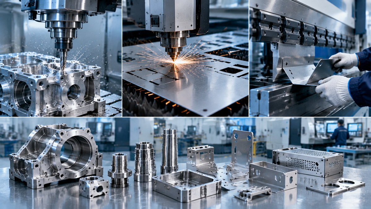
There is no single number that applies to every project. In many general machining applications, a tolerance around ±0.05 mm to ±0.13 mm may be suitable for standard features. A requirement around ±0.025 mm, ±0.01 mm, or tighter is often considered a tight tolerance because it requires increased process control and more capable inspection.
It can be achievable for selected features, but it depends on the material, geometry, machine capability, fixture stability, cutting process, tool condition, temperature, and inspection method. A supplier should evaluate the full part design before confirming this requirement.
Tight tolerance machining can require more setup time, refined workholding, slower finishing passes, more frequent tool management, specialized equipment, detailed inspection, and a higher risk of rejected parts. These factors increase both machining time and quality-control effort.
No. Tight tolerances should be applied only to dimensions that directly affect fit, sealing, alignment, movement, safety, or product appearance. Applying close limits to non-critical features usually increases cost without adding functional value.
Dimensional tolerance controls the allowable variation in size, such as the diameter of a hole or the length of a feature. Geometric tolerance controls form, orientation, location, and movement relationships, such as flatness, perpendicularity, position, profile, or runout.
Start with the feature's function. If a small variation could prevent assembly, create leakage, cause vibration, reduce accuracy, or affect product safety, tighter control may be needed. If the feature has enough clearance or does not influence performance, a standard tolerance is usually more practical.
Yes, but tolerance capability depends on material thickness, bend angle, bend radius, tooling, springback, grain direction, feature location, and forming method. In some cases, laser cutting and bending can be combined with CNC machining for the most critical features.
1. American Society of Mechanical Engineers. [Y14.5 Dimensioning and Tolerancing]. This standard provides rules, symbols, definitions, requirements, and recommended practices for communicating geometric dimensioning and tolerancing requirements.
2. International Organization for Standardization. [ISO 2768 — Geometrical Product Specifications]. This standard family provides general tolerance principles and tolerance classes for applicable machined and sheet-metal workpieces.
3. National Institute of Standards and Technology. [Metrological Traceability: Frequently Asked Questions]. This resource explains traceability through calibration chains and the separate importance of measurement uncertainty.
4. National Institute of Standards and Technology. [Uncertainties in Dimensional Measurements Made at Nonstandard Temperatures]. This publication discusses the effects of temperature and thermal expansion on dimensional measurement uncertainty.
5. National Institute of Standards and Technology. [Dimensional Measurement Traceability of 3D Imaging Data]. This report discusses the relationship between measurement uncertainty, traceability, and meaningful manufacturing inspection.
6. Protolabs. [Understanding CNC Machining Tolerances]. This technical resource discusses practical CNC tolerance considerations and the relationship between tighter requirements, manufacturability, and inspection.


