Views: 287 Author: U-Need Publish Time: 2026-10-04 Origin: Site
Content Menu
● What Is Dimensional Tolerance in CNC Machining?
>> Common Types of Dimensional Tolerance
>> Why Dimensional Tolerance Matters
● What Is Geometric Tolerance?
>> The Five Main Categories of Geometric Tolerances
>> Example of a Geometric Tolerance
● Dimensional Tolerance vs Geometric Tolerance: Core Differences
>> Example: A Shaft and Bearing Assembly
● How Dimensional Tolerances Work in Precision CNC Parts
>> Dimensional Tolerance and Engineering Fits
● How Geometric Tolerances Protect CNC Part Function
>> Form Tolerances in CNC Machining
>> Orientation Tolerances in CNC Machining
>> Location Tolerances in CNC Machining
>> Runout Tolerances in CNC Machining
● Why Parts Can Pass Dimensional Inspection but Fail in Assembly
>> Common Manufacturing Failure Scenarios
>> Functional Tolerance Starts With Product Use
● Cost Considerations for CNC Tolerances
>> The Risk of Over-Tolerancing
● Inspection Methods for Dimensional and Geometric Tolerances
>> Measuring Dimensional Tolerances
>> Measuring Geometric Tolerances
● How to Specify Tolerances on a CNC Machining Drawing
>> Practical Tolerance Specification Checklist
● Industry Example: CNC-Machined Electronics Housing
● When to Use Dimensional Tolerance
● When to Use Geometric Tolerance
● Precision Tolerance Support for Custom Manufacturing
● Summary
>> What is the main difference between dimensional tolerance and geometric tolerance?
>> Can a CNC part meet dimensional tolerance but fail geometric tolerance?
>> Is geometric tolerance more expensive than standard dimensional tolerance?
>> What is the most common geometric tolerance in CNC machining?
>> Why are datums important in geometric tolerance?
>> Should every dimension on a CNC drawing have a tight tolerance?
>> What inspection equipment is used for geometric tolerances?
>> Which standards are commonly used for geometric tolerancing?
In precision CNC machining, a component can meet every stated size dimension and still fail during assembly. This is why the difference between dimensional tolerance and geometric tolerance matters to design engineers, purchasing teams, product developers, and manufacturers.
Dimensional tolerance controls size. Geometric tolerance controls shape, orientation, location, and rotational behavior. Both are essential in precision manufacturing, but they protect different aspects of a part's function.
A bore may have the correct diameter but be positioned incorrectly. A shaft may have the correct length but excessive runout. A mounting surface may meet its thickness requirement but lack the flatness needed for sealing or heat transfer.
For global manufacturers, distributors, and brands, a well-defined tolerance strategy influences more than component quality. It affects assembly performance, production yield, machining cost, inspection planning, lead time, and long-term supply consistency.
U-Need supports customers with custom precision parts machining, mold manufacturing, sheet metal fabrication, and other end-to-end manufacturing solutions. In real production projects, one issue appears repeatedly: a drawing may include very tight dimensional tolerances but omit the geometric controls needed to ensure functional assembly.
This guide explains dimensional tolerance vs geometric tolerance in precision CNC parts, including practical applications, inspection methods, cost considerations, and drawing-specification recommendations.

Dimensional tolerance defines the acceptable variation in the measurable size of a feature.
It answers a direct manufacturing question:
> How much larger or smaller than the nominal dimension may this feature be?
This means the completed shaft must measure between:
- Maximum allowable size: 10.05 mm
- Minimum allowable size: 9.95 mm
A shaft measuring 10.07 mm is oversized. A shaft measuring 9.92 mm is undersized. Either condition may affect the intended fit, assembly, or performance of the final product.
Dimensional tolerances are commonly shown in several formats.
| Tolerance Format | Example | Meaning | Common Application |
|---|---|---|---|
| Bilateral tolerance | 20.00 ± 0.10 mm | Variation is allowed above or below nominal size | General machined lengths, widths, and thicknesses |
| Unilateral tolerance | 20.00 +0.05 / -0.00 mm | Variation is permitted in one direction only | Bearing seats, press-fit features, critical shafts |
| Limit dimension | 19.95–20.05 mm | Maximum and minimum sizes are specified directly | Production drawings and inspection plans |
| Basic dimension | 25.00 mm in a box | A theoretically exact value used with geometric controls | Hole patterns and functional feature locations |
| General tolerance | ISO 2768 or drawing title block | Default tolerance for unspecified dimensions | Noncritical features |
Dimensional tolerance is often applied to:
- Shaft diameters
- Bore diameters
- Overall part lengths
- Plate thicknesses
- Slot widths
- Wall thicknesses
- Counterbore depths
- Thread depths
- Keyway widths
- Distances between edges
Size affects how components fit and work together.
For example:
- A bearing bore that is too large may allow unwanted movement, vibration, and wear.
- A hole that is too small may prevent a bolt or dowel pin from entering.
- A sheet metal flange that is too short may not align with a mating enclosure.
- A molded snap feature that is oversized may not engage correctly.
- A shaft with an undersized diameter may create excessive clearance in a coupling.
However, dimensional tolerance does not fully define a part's functional condition.
A hole can have the correct diameter and still be unusable if it is placed off-center, drilled at the wrong angle, or located on a warped surface. This is where geometric tolerance becomes necessary.
Geometric tolerance controls the permissible variation in a feature's geometry.
It does not only ask whether a feature is the correct size. It also defines whether the feature has the correct:
- Form
- Orientation
- Location
- Profile
- Rotational behavior
Geometric tolerance is commonly communicated through standardized symbols, feature control frames, and datum references. It is often called GD&T, short for geometric dimensioning and tolerancing.
Instead of simply measuring a hole from two edges, a geometric control can define how accurately that hole must relate to the part's functional mounting surfaces, centerline, or assembly axis.
| GD&T Category | What It Controls | Typical Controls | CNC Machining Example |
|---|---|---|---|
| Form | The intrinsic shape of a feature | Straightness, flatness, circularity, cylindricity | A sealing surface must remain flat |
| Profile | The 2D or 3D contour of a feature | Profile of a line, profile of a surface | A complex enclosure contour |
| Orientation | The angular relationship to a datum | Parallelism, perpendicularity, angularity | A mounting face perpendicular to a bore |
| Location | The position of features relative to datums | Position, concentricity, symmetry | Bolt holes aligned with a reference axis |
| Runout | Surface variation during rotation | Circular runout, total runout | A rotating shaft or spindle journal |
Imagine a machined aluminum mounting plate with four bolt holes.
This means the axis of each hole must stay within a cylindrical tolerance zone with a diameter of 0.20 mm. The hole locations are evaluated from the designated datum system.
The diameter tolerance confirms that the holes are large enough. The position tolerance confirms that they are located correctly for assembly.
Without positional control, each hole could meet the diameter specification but still prevent the mounting plate from aligning with its mating component.
The most important distinction is straightforward:
- Dimensional tolerance answers: Is the feature the right size?
- Geometric tolerance answers: Is the feature correctly shaped, oriented, positioned, or rotating as intended?
The two types of tolerance are not alternatives. They work together to define the actual functional requirements of a precision CNC part.
| Comparison Factor | Dimensional Tolerance | Geometric Tolerance |
|---|---|---|
| Main purpose | Controls feature size | Controls feature geometry and functional relationship |
| Typical measurement | Length, width, diameter, thickness, depth | Flatness, perpendicularity, position, profile, runout |
| Reference method | Usually measured directly from a stated dimension | Often measured relative to one or more datums |
| Drawing format | Plus/minus values, limits, tolerance notes | Symbols and feature control frames |
| Functional focus | Fit, clearance, interference, material thickness | Alignment, sealing, rotation, assembly, interchangeability |
| Example | Ø12.00 ± 0.03 mm | Position Ø0.10 mm relative to A-B-C |
| Common inspection tools | Calipers, micrometers, pin gauges, bore gauges | CMMs, vision systems, height gauges, fixtures, roundness testers |
| Common failure risk | Feature is too large or too small | Features do not align, seal, rotate, or assemble correctly |
| Cost influence | Tighter size limits increase machining and inspection effort | Complex controls can increase setup, fixturing, and metrology requirements |
| Best use | Controlling individual dimensions | Controlling relationships between multiple features |
Consider a stainless-steel CNC-machined shaft designed to operate inside a bearing.
The drawing may require:
- Shaft diameter: Ø20.00 ± 0.01 mm
- Cylindricity: 0.005 mm
- Total runout: 0.010 mm relative to datum A
Each requirement protects a different function.
| Requirement | Functional Purpose |
|---|---|
| Diameter tolerance | Maintains the intended bearing fit |
| Cylindricity tolerance | Keeps the shaft surface consistent along its full length |
| Total runout tolerance | Supports stable and smooth rotation around the datum axis |
| Surface roughness requirement | Reduces friction, wear, and possible seal damage |
A shaft may meet its diameter tolerance but still have excessive runout. In that situation, the shaft may create vibration, uneven bearing loading, noise, seal wear, or reduced service life.
This is why high-performance rotating components require more than correct dimensions. They require control over the part's functional geometry.
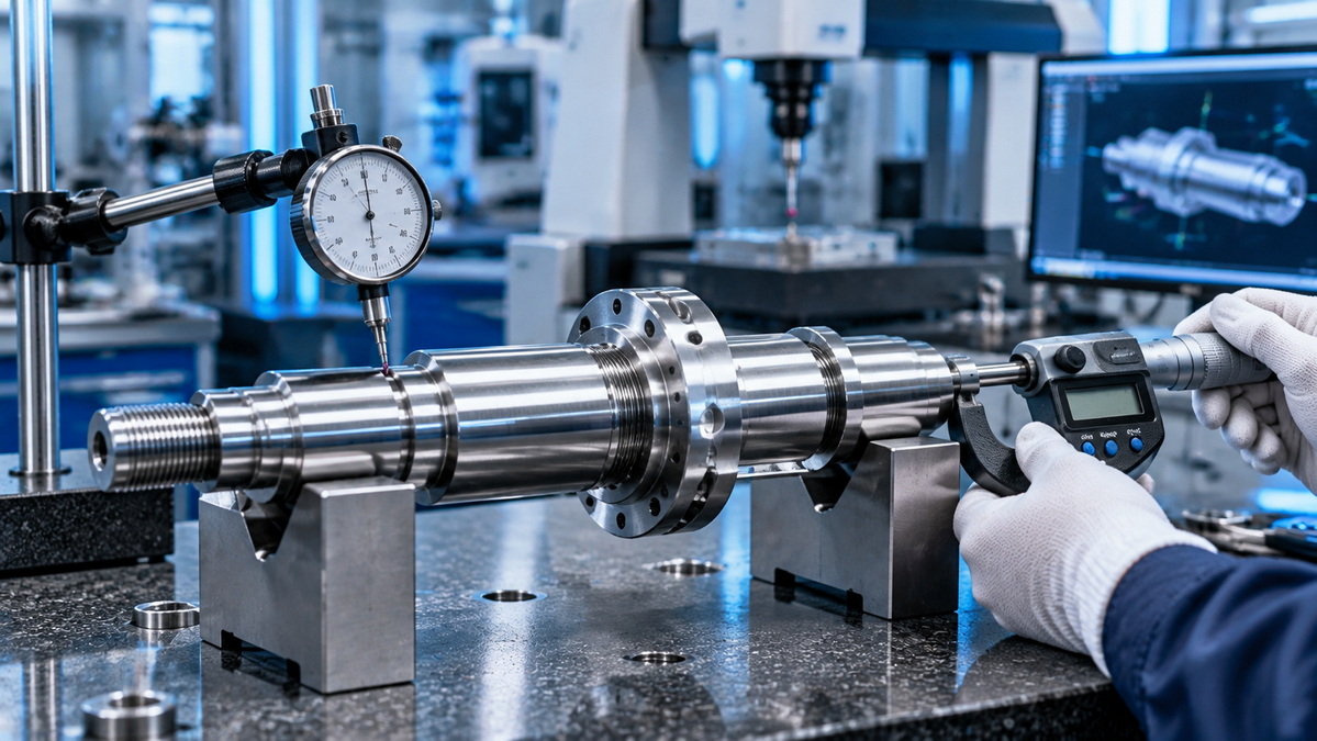
Dimensional tolerance is often the first layer of quality control because it is relatively easy to understand and measure.
A CNC machining drawing may specify:
- Overall length: 100.00 ± 0.10 mm
- Bore diameter: Ø12.00 H7
- Slot width: 6.00 +0.02 / -0.00 mm
- Wall thickness: 2.50 ± 0.05 mm
These requirements establish a manufacturing range. During production, the machinist or inspector checks whether the actual dimension remains within the allowed limits.
For mating CNC-machined components, tolerance selection determines whether parts have clearance, transition, or interference fit.
| Fit Type | Relationship Between Mating Parts | Typical Application |
|---|---|---|
| Clearance fit | The hole is always larger than the shaft | Sliding parts, removable pins, rotating shafts |
| Transition fit | The assembly may have small clearance or small interference | Accurate location, hubs, moderate-force assembly |
| Interference fit | The shaft is intentionally larger than the hole | Press-fit gears, permanent hubs, bearing seats |
For example, a bearing seat may require a controlled shaft diameter to prevent movement during operation. A removable locating pin may require a clearance fit so that it can be inserted and removed without damage.
The goal is not to choose the tightest tolerance possible. The goal is to select the most functional and economical tolerance for the real application.
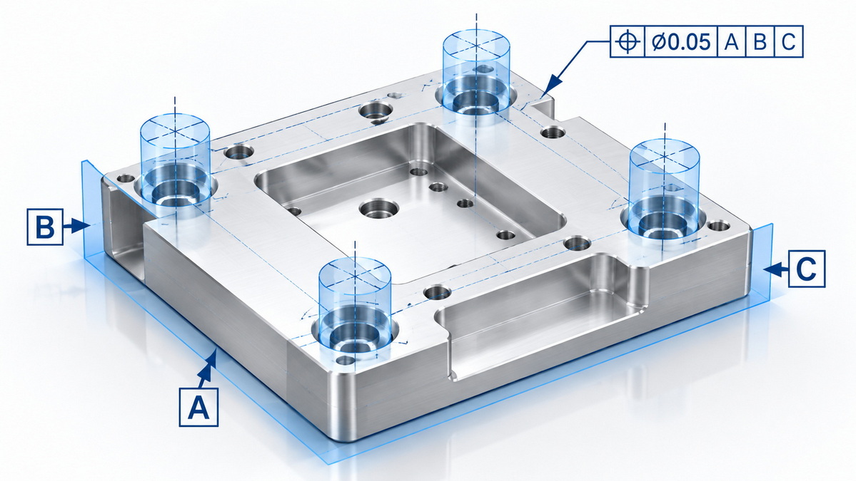
Geometric tolerances become especially valuable when several features must work together.
A CNC-machined component may include:
- A bore that must align with a mating shaft
- A sealing face that must remain flat
- A hole pattern that must match another component
- A flange that must stay perpendicular to a central axis
- A rotating surface that must minimize runout
- A profile that must match a mating housing or cover
Traditional plus/minus dimensions may not clearly communicate these functional relationships. Geometric controls provide a more direct and repeatable method.
Form tolerances control the shape of a single feature without needing a datum reference.
Common form controls include:
- Straightness
- Flatness
- Circularity
- Cylindricity
Flatness is widely used for sealing faces, precision mounting plates, heat-sink contact surfaces, and mating interfaces.
For example, an electronics enclosure cover may have the correct wall thickness but still leak if the gasket-contact face is not sufficiently flat. A thermal interface plate may have the right dimensions but deliver poor heat transfer if the contact surface is warped.
Orientation tolerances control the angular relationship of a feature to a datum.
The most common orientation controls are:
- Parallelism
- Perpendicularity
- Angularity
For example, a threaded hole may need to be perpendicular to a mounting face. If the hole is tilted, a screw may not seat properly. This can create uneven clamping force, interfere with nearby parts, damage threads, or create an unreliable assembly.
Location tolerances are critical where features must align with mating components.
The most common control is position tolerance.
Position tolerance is commonly used for:
- Bolt-hole patterns
- Dowel pin holes
- Bearing bores
- Threaded hole locations
- Electrical connector ports
- Machined slots
- Locating pockets
- Internal component mounting points
Compared with coordinate plus/minus tolerancing, position tolerance can define the functional location zone more clearly. It may also offer a practical manufacturing allowance when material condition modifiers are correctly applied.
Runout is especially important for rotational components, including:
- Motor shafts
- Spindles
- Pulleys
- Gear shafts
- Rotary seals
- Precision rollers
- Medical device components
- Pump and valve parts
Circular runout controls variation at individual cross-sections during rotation.
Total runout controls the accumulated variation across the full rotating surface.
For a shaft with bearing journals and sealing surfaces, total runout is often used to support smooth rotation, proper bearing performance, and reduced seal wear.
A part can pass a dimensional inspection report and still fail during assembly.
This often occurs because dimensional measurements alone do not fully evaluate the relationship between features.
For example, a supplier may verify that all holes meet the required diameter. However, if the holes are slightly misplaced, the part may not align with the mating component.
| Manufacturing Issue | Dimensional Result | Geometric Issue | Functional Consequence |
|---|---|---|---|
| Bolt holes are correctly sized | Hole diameter passes | Hole positions drift | Assembly holes do not align |
| Shaft diameter is within range | Diameter passes | Shaft has excessive runout | Vibration and bearing wear |
| Sealing face thickness is correct | Thickness passes | Surface is not flat | Leakage or poor thermal transfer |
| Bore diameter is correct | Diameter passes | Bore axis is not perpendicular | Misalignment with mating shaft |
| Sheet metal panel dimensions pass | Length and width pass | Bent flange angle varies | Enclosure does not close correctly |
| Mold component sizes pass | Size passes | Core and cavity alignment is incorrect | Flash, mismatch, or uneven wall thickness |
The best tolerance strategy begins with function, not with measurement convenience.
Before assigning tolerances, review the following questions:
1. Which features locate the part during assembly?
2. Which surfaces seal, slide, rotate, or transfer heat?
3. Which holes must align with mating components?
4. Which surface or axis is the true functional datum?
5. What failure could occur if a feature shifts, tilts, warps, or rotates?
6. Which inspection method can verify the requirement consistently?
7. Can the selected tolerance be produced reliably at the expected volume?
These questions often show that both size tolerance and geometric tolerance are needed.
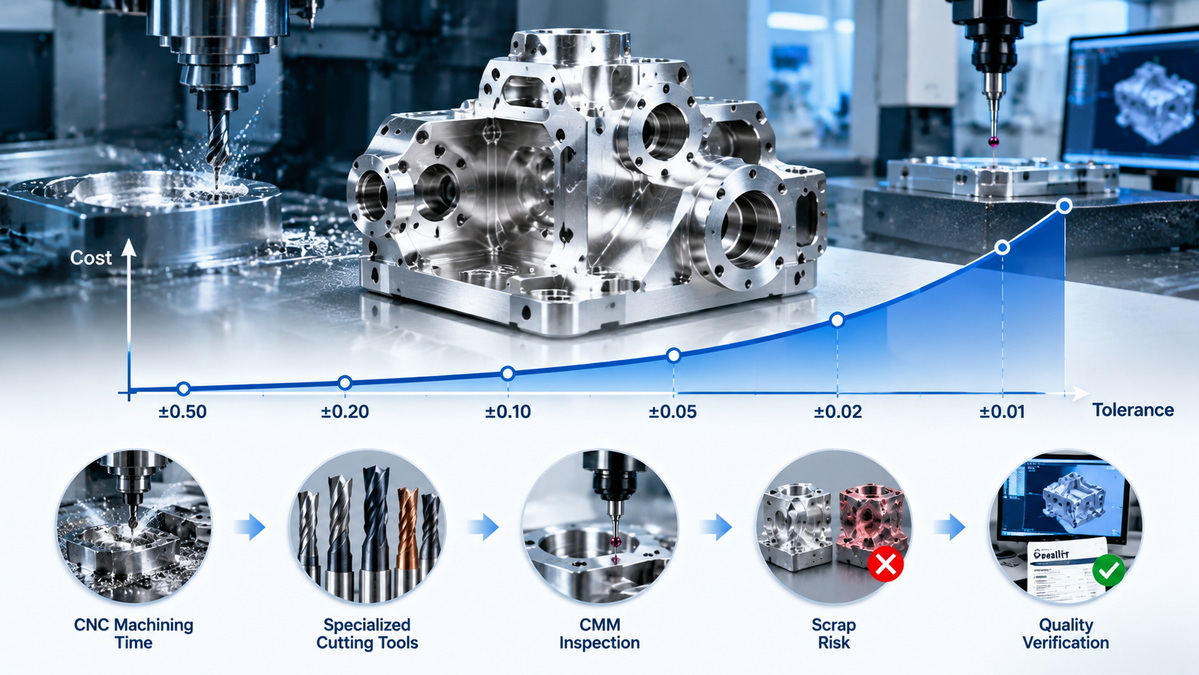
A tighter tolerance does not automatically mean a better part.
Unnecessary precision can raise cost without improving performance.
Tight machining requirements may require:
- Higher-grade or more stable raw material
- More machining passes
- Lower cutting speeds
- More specialized cutting tools
- Increased tool replacement
- Temperature-controlled inspection
- Frequent in-process measurement
- Custom fixtures
- Advanced measuring equipment
- More complex programming
- Higher scrap risk
- Longer production lead times
As required tolerances become tighter, the measurement system must also be capable of proving compliance with sufficient accuracy and repeatability. Precision manufacturing depends on both machining capability and metrology capability.
A drawing may define a hole location with coordinate dimensions such as:
- X = 50.00 ± 0.05 mm
- Y = 30.00 ± 0.05 mm
This may seem highly precise. However, it can create a rectangular tolerance zone that does not always match the real function of the hole.
When properly applied, geometric tolerance can create a functional tolerance zone that supports assembly while avoiding unnecessary rejection of acceptable parts.
The objective is not to make every number smaller.
The objective is to specify only the precision needed to support:
- Product performance
- Safety
- Interchangeability
- Reliable assembly
- Sealing performance
- Rotational stability
- Long-term durability
- Cost-effective production
Inspection should be considered during the early design stage.
A tolerance that cannot be measured consistently may lead to disagreements between design teams, suppliers, inspectors, and end users.
Common methods for dimensional inspection include:
- Digital calipers for general external dimensions
- Outside micrometers for precision shaft diameters
- Bore gauges for internal diameters
- Pin gauges for small holes
- Thread gauges for threaded features
- Height gauges for linear dimensions from a datum surface
- Go/no-go gauges for high-volume verification
- Optical systems for small or delicate features
Geometric tolerances often require more advanced inspection tools.
Common options include:
- Coordinate measuring machines
- Vision measurement systems
- Optical comparators
- Surface plates and height gauges
- Granite inspection tables
- Dial indicators
- Roundness testers
- Form measuring instruments
- Dedicated functional gauges
- Custom inspection fixtures
A geometric tolerance is only meaningful when the datum system is clearly defined and correctly reproduced during inspection.
For example, if datum A is the primary mounting face, the part should be established against that face before inspecting the position of its holes or bores.
If the part is measured from a different surface, the inspection result may not reflect how the component performs in the final assembly.
A complete inspection report should identify:
- Drawing number and revision
- Material and part number
- Measurement equipment used
- Calibration status
- Datum setup
- Sample quantity
- Actual measured values
- Pass or fail result
- Inspector name
- Inspection date
For critical applications, a first article inspection report is often used to confirm that the first production sample meets all important dimensional and geometric requirements.
A well-prepared drawing gives a manufacturer enough information to machine, inspect, and validate the part consistently.
It should protect critical functional requirements while avoiding unnecessary restrictions.
1. Identify functional features.
Highlight the surfaces, bores, holes, threads, slots, and profiles that influence assembly, motion, sealing, strength, or appearance.
2. Choose meaningful datums.
Select stable and functional surfaces as primary, secondary, and tertiary datums.
3. Apply size tolerances where feature size matters.
Control shaft diameters, bore diameters, widths, lengths, wall thicknesses, and depths where fit is important.
4. Apply geometric controls where feature relationships matter.
Use position, flatness, perpendicularity, parallelism, profile, and runout where needed.
5. Avoid unnecessary tight tolerances.
Do not apply high-precision requirements to nonfunctional or cosmetic areas unless there is a clear performance reason.
6. Define surface finish requirements.
Surface roughness can affect sealing, sliding, coating adhesion, friction, wear, and visual quality.
7. Specify material and post-processing.
Include material grade, heat treatment, anodizing, plating, passivation, painting, polishing, or other finishing requirements.
8. Confirm inspection feasibility.
Ensure the supplier can inspect the tolerance with a repeatable method and appropriate datum setup.
9. Review tolerance stack-up.
Evaluate how variation between multiple components may affect the final assembly.
10. Review critical features before production.
Discuss important tolerance requirements, measurement methods, and acceptance criteria before machining begins.
Consider a CNC-machined aluminum housing used in industrial automation equipment.
The housing includes:
- A mounting base
- A gasket groove
- Connector cutouts
- Internal PCB standoffs
- Threaded mounting holes
- A cover interface
- Heat-transfer surfaces
A dimensional-only drawing may define the part's overall length, width, height, wall thickness, hole diameters, and gasket-groove width.
However, those dimensions alone may not protect the actual performance of the enclosure.
A more functional drawing can include the following controls.
| Feature | Recommended Control | Functional Reason |
|---|---|---|
| Base mounting surface | Flatness | Supports stable mounting and effective heat transfer |
| PCB standoff locations | Position relative to datums | Aligns the PCB with connectors and cover features |
| Connector cutouts | Profile tolerance | Supports connector fit and consistent visual appearance |
| Threaded holes | Position and perpendicularity | Helps screws engage correctly and clamp evenly |
| Cover sealing face | Flatness and surface finish | Supports gasket compression and ingress protection |
| Critical enclosure wall | Thickness tolerance | Maintains strength, weight control, and machining feasibility |
This approach focuses precision on the features that influence assembly and performance.
It avoids increasing machining difficulty on surfaces that do not require exceptional control.
Use dimensional tolerance when the primary concern is the actual size of an individual feature.
Typical examples include:
- Shaft diameter for a bearing or bushing fit
- Hole diameter for a fastener or dowel pin
- Slot width for a tab, key, or electrical connector
- Plate thickness for strength or clearance
- Overall length for installation space
- Thread depth for fastener engagement
- Wall thickness for rigidity or weight reduction
- Counterbore depth for screw-head clearance
Dimensional tolerances are most effective when a feature can be evaluated independently and its functional requirement depends mainly on size.
Use geometric tolerance when the relationship between features affects product performance, assembly, sealing, rotation, alignment, or visual consistency.
Typical applications include:
- Bolt-hole pattern alignment
- Dowel pin location
- Bearing bore position
- Perpendicularity of a bore to a mounting surface
- Flatness of a heat-sink interface
- Parallelism of guide rails
- Profile control of a complex machined contour
- Total runout of a rotating shaft
- Orientation of a sheet metal flange
- Alignment of mold inserts, cores, and cavities
Geometric controls are particularly valuable when a part interacts with another part. They help ensure that separately manufactured components can assemble and operate consistently.
Precision manufacturing requires more than machining a part to a nominal dimension. It requires a clear understanding of function, material behavior, process capability, inspection methods, and production repeatability.
U-Need provides manufacturing support for custom precision parts, injection molds, stamping dies, cold-forging dies, and sheet metal fabrication projects.
A practical tolerance review can include:
- Drawing and GD&T review before quotation
- Identification of critical-to-function features
- Material and process recommendations
- Manufacturability feedback
- Datum and inspection-method evaluation
- Prototype and low-volume validation
- First article inspection support
- In-process quality verification
- Final inspection planning
- Production preparation for repeatability and scale
Early discussion of critical dimensions, geometric controls, surface requirements, and inspection expectations helps prevent avoidable production issues later.
Dimensional tolerance and geometric tolerance are complementary tools for defining precision CNC parts.
Dimensional tolerance ensures that a feature is the correct size. It controls values such as length, width, thickness, depth, and diameter.
Geometric tolerance ensures that a feature has the correct shape and relationship to other features. It controls flatness, straightness, perpendicularity, parallelism, position, profile, and runout.
A part that meets its dimensional tolerance may still fail if holes do not align, a sealing surface is not flat, a bore is tilted, or a shaft has excessive runout.
The most reliable approach is to define tolerances according to the real function of the part. Use dimensional controls for fit and feature size. Use geometric controls for alignment, orientation, sealing, rotation, and assembly relationships.
For custom precision components, a clear drawing, practical datum strategy, realistic tolerance selection, and repeatable inspection plan create the foundation for stable quality and efficient manufacturing.
Dimensional tolerance controls the allowable variation in a feature's size, such as diameter, length, width, thickness, or depth. Geometric tolerance controls feature form, orientation, location, profile, and runout, often in relation to one or more datums.
Yes. A hole may have the correct diameter but be located incorrectly. A shaft may meet its diameter requirement but have excessive runout. A mounting face may have the correct thickness but insufficient flatness.
Not always. Some geometric controls require advanced inspection equipment or additional setup time. However, properly applied geometric tolerance can reduce cost by defining the actual functional requirement more clearly and preventing unnecessary rejection of acceptable parts.
Position tolerance is one of the most common controls because it defines the allowable location of holes, bores, threads, slots, dowel pins, and feature patterns relative to functional datums.
Datums create a consistent reference system for manufacturing and inspection. They represent how the part is located in the final assembly. Without clear datums, different inspectors or suppliers may measure the same feature differently.
No. Tight tolerances should be applied only where needed for fit, function, assembly, safety, sealing, rotation, or interchangeability. Over-tolerancing increases machining cost, inspection effort, lead time, and scrap risk.
Depending on the feature and tolerance requirement, manufacturers may use coordinate measuring machines, vision systems, height gauges, surface plates, dial indicators, roundness testers, custom fixtures, or functional go/no-go gauges.
ASME Y14.5 is widely used for geometric dimensioning and tolerancing in the United States and global supply chains. ISO 1101 is an important international standard for geometrical tolerancing, including controls for form, orientation, location, and runout.
1. American Society of Mechanical Engineers. "Y14.5: Dimensioning and Tolerancing."
[https://www.asme.org/codes-standards/find-codes-standards/y14-5-dimensioning-tolerancing]
2. International Organization for Standardization. "ISO 1101:2017 — Geometrical Product Specifications (GPS): Geometrical Tolerancing."
[https://www.iso.org/standard/66777.html]
3. British Standards Institution. "ISO 1101 — Geometrical Product Specifications and Tolerancing."
4. National Institute of Standards and Technology. "Length and Dimensional Measurements at NIST."
[https://pmc.ncbi.nlm.nih.gov/articles/PMC4865292/]
5. International Organization for Standardization. "ISO 1101:2017 International Standard Overview."
[https://cdn.standards.iteh.ai/samples/66777/accb9f85e8b64f108b5c205a0471539c/ISO-1101-2017.pdf]


