Views: 241 Author: U-Need Publish Time: 2026-09-24 Origin: Site
Content Menu
● What Are High-Tolerance CNC Precision Parts?
>> Common Characteristics of High-Tolerance CNC Parts
>> General Tolerances for Standard Components
● High-Tolerance CNC Precision Parts vs Standard Parts
● Why Tight Tolerances Increase Manufacturing Cost
>> Key Cost Drivers of High-Tolerance Machining
● When Engineers Should Specify High Tolerances
>> Features That Commonly Need Tight Tolerances
>> Features That Often Do Not Need Tight Tolerances
● How to Specify Tolerances Effectively
>> Identify Critical-to-Function Features
>> Establish Functional Datums
>> Use Geometric Controls for Functional Relationships
>> Consider Maximum Material Condition
● Perform Tolerance Stack-Up Analysis
>> Typical Factors in a Tolerance Stack-Up
>> Example: Mounting Plate Assembly
● Match Tolerance Requirements to Manufacturing Processes
>> Mold Manufacturing and Injection Molding
● Measurement Is Part of the Tolerance Strategy
● Common Tolerancing Mistakes to Avoid
>> Over-Tolerancing Every Feature
>> Tolerancing Before Understanding Assembly
>> Forgetting Surface Treatment Effects
>> Using Dimensions That Cannot Be Measured Easily
>> Not Sharing Functional Intent With Suppliers
● How U-Need Supports Tolerance-Driven Manufacturing
● Summary
● FAQ
>> What is a high-tolerance CNC precision part?
>> Are high-tolerance CNC parts more expensive than standard parts?
>> When should engineers use general tolerances?
>> Why are datums important in CNC machining drawings?
>> What is tolerance stack-up analysis?
>> Can sheet metal parts achieve tight tolerances?
>> How can a manufacturer verify tight tolerances?
When comparing high-tolerance CNC precision parts vs standard parts, engineers should not begin by asking how tight a supplier can machine a feature. The more important question is: What level of variation can the part allow while still meeting fit, function, safety, assembly, and long-term performance requirements?
A tighter tolerance is not automatically better. It can improve interchangeability, alignment, sealing, and motion accuracy when applied to the right feature. However, it can also increase machining time, inspection requirements, material waste, production risk, and total manufacturing cost when used unnecessarily.
For global manufacturers, distributors, and product-development teams, the goal is to create drawings that are clear, functional, measurable, and practical to manufacture. U-Need supports this process through custom precision parts machining, mold manufacturing, sheet metal fabrication, laser cutting, bending, stamping, and other end-to-end manufacturing solutions in China.
This article explains the real difference between high-tolerance CNC precision parts and standard parts, the cost and quality implications of each option, and how engineers can specify tolerances more effectively.
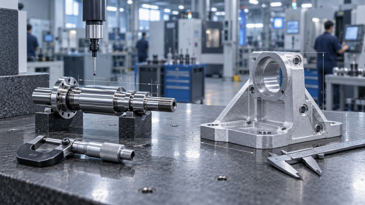
High-tolerance CNC precision parts are components produced within narrow allowable limits for size, form, orientation, location, or surface condition.
This allows the diameter to range from 9.9 mm to 10.1 mm. The total variation is 0.2 mm, which is substantially wider.
High-tolerance CNC machining is generally required when a part must achieve highly controlled performance in an assembly. Common examples include precision shafts, bearing seats, sealing surfaces, optical mounts, valve components, medical equipment parts, robotic joints, aerospace mechanisms, and high-speed rotating parts.
High-tolerance parts often require more than advanced CNC equipment. They also depend on a stable and controlled manufacturing system.
Typical requirements include:
- High-rigidity CNC milling and turning machines
- Precision cutting tools and optimized machining parameters
- Stable fixtures and custom soft jaws
- Careful control of clamping force
- In-process dimensional checks
- Precision measuring equipment
- Detailed inspection plans
- Clear datum structures
- Geometric dimensioning and tolerancing
- Material traceability when required
- Controlled post-processing procedures
A feature may be easy to machine once during a prototype run but difficult to reproduce consistently across hundreds or thousands of production parts. This is why repeatability matters as much as individual-part accuracy.
Standard parts are components manufactured to broader and more general tolerance requirements. These parts may still be durable, well-machined, and suitable for demanding industrial applications. The key difference is that their performance does not depend on extremely narrow variation limits.
Standard parts are often used when there is sufficient clearance in the assembly, when exact alignment is not critical, or when a feature does not directly affect movement, sealing, safety, or product performance.
Examples of standard CNC machined or fabricated parts include:
- Mounting brackets
- Machine covers
- Protective housings
- Basic flanges
- General-purpose spacers
- Sheet metal panels
- Non-critical frames
- Equipment supports
- Cosmetic enclosures
- Access plates
- Cable-management brackets
- Simple mounting plates
A standard sheet metal bracket may only need mounting holes large enough to allow bolts to pass through easily. If the assembled product has sufficient clearance, extremely tight hole-position tolerances may not improve performance.
Instead, they may increase the supplier's machining and inspection workload without creating meaningful value for the final product.
Standard parts often use general tolerance notes rather than assigning an individual tolerance to every dimension.
A drawing may include a title-block note such as:
- Linear dimensions without individual tolerances follow a general tolerance standard
- Angular dimensions use a specified general tolerance class
- Sheet metal dimensions follow agreed fabrication tolerances
- Non-critical edges are deburred
- Non-critical surfaces use a standard finish requirement
This approach makes drawings easier to read and helps manufacturers focus additional attention on the features that truly affect function.
The following comparison helps explain where each approach is most appropriate.
| Comparison Area | High-Tolerance CNC Precision Parts | Standard Parts |
|---|---|---|
| Main purpose | Controls critical functional variation | Meets general size and assembly requirements |
| Typical use | Precision mechanisms, sealing systems, bearing interfaces, aerospace parts, medical equipment | Brackets, covers, housings, supports, panels, non-critical hardware |
| Tolerance range | Narrow dimensional and geometric limits | Broader dimensional limits |
| Drawing requirements | Detailed dimensions, datums, feature controls, inspection criteria | General tolerances and simplified dimensioning |
| Machining process | More controlled setup, tooling, finishing, and adjustment | Conventional machining or fabrication methods |
| Inspection method | CMM, precision gauges, air gauges, full reports, increased inspection frequency | Calipers, go/no-go gauges, visual checks, sampling inspection |
| Manufacturing time | Longer due to setup, machining, and inspection | Shorter for non-critical features |
| Production cost | Higher due to process control and scrap risk | Lower when broader variation is acceptable |
| Supplier selection | Requires proven precision-machining and measurement capability | Available from a wider range of manufacturers |
| Main risk | Over-specification can increase cost and lead time | Under-specification can cause fit or function problems |
The correct choice is not "precision part" or "standard part." The correct choice is the level of control that supports the intended application.
Tighter tolerances can increase cost quickly because they may require a different manufacturing route, more machine time, more inspection, and a higher level of process control.
A hole with a broad tolerance may be produced by drilling. A tighter hole may require drilling, boring, reaming, and final measurement. A very precise bore may require honing or grinding after machining.
Similarly, a basic flat surface may be machined in one operation. A critical sealing face may require finish milling, grinding, flatness inspection, and careful handling to prevent damage.
- Additional machining operations such as reaming, boring, grinding, honing, lapping, or polishing
- Lower cutting speeds to improve surface finish and dimensional control
- More frequent tool-offset adjustments
- Special cutting tools and fixtures
- Multiple setups and alignment checks
- Increased inspection frequency
- More expensive gauges and measurement equipment
- Higher scrap risk
- Longer production lead times
- Greater operator skill requirements
- Reduced flexibility in process planning
A tight tolerance can also be affected by material condition. Aluminum, stainless steel, carbon steel, titanium, brass, and engineering plastics behave differently during machining.
Thin-wall parts may deform when clamped. Long shafts may bend under cutting force. Heat-treated materials may change size after processing. Large parts may expand or contract with temperature changes. Sheet metal may experience springback after bending.
The manufacturing process must account for these variables before a tight tolerance can be achieved consistently.
High tolerances should be applied only when a feature has a clear relationship to product performance.
The strongest engineering drawings distinguish between critical features and non-critical features. Not every surface, hole, edge, or dimension needs the same level of control.
High-tolerance CNC precision machining may be appropriate for:
- Bearing bores and bearing seats
- Shaft journals
- Press-fit components
- Interference-fit features
- Sliding-fit components
- Hydraulic and pneumatic sealing surfaces
- Valve bodies and fluid-control components
- Gear mounting features
- High-speed rotating assemblies
- Robotic arms and motion-control systems
- Precision optical mounts
- Medical-device components
- Aerospace and defense components
- Electrical connector alignment features
- Locating pins and locating holes
- Critical mold cavity and core inserts
- Tooling components
- Precision die components
- Functional mating surfaces
For example, a bearing housing bore needs controlled size and geometry because the bearing must seat correctly. If the bore is too large, the bearing may move during operation. If it is too small, the bearing may be difficult to install or may experience unwanted stress.
In contrast, the outer dimensions of the same housing may allow a broader tolerance if those dimensions do not affect mounting or assembly.
Broader tolerances may be acceptable for:
- External cosmetic dimensions
- Non-mating surfaces
- Protective covers
- General mounting tabs
- Non-functional chamfers
- Non-critical cutouts
- Unused surface areas
- Loose-clearance mounting holes
- Packaging-related dimensions
- Non-contact sheet metal edges
This selective approach helps engineers protect product performance without increasing production cost across the entire component.
Effective tolerancing begins with function. Engineers should define what each feature must accomplish before assigning a numerical tolerance.
Each feature should be reviewed according to the consequences of variation.
| Feature Type | Key Question | Recommended Approach |
|---|---|---|
| Critical-to-function feature | Will variation affect safety, sealing, movement, accuracy, or performance? | Use individual tolerances and geometric controls where appropriate |
| Critical-to-assembly feature | Will variation affect installation, alignment, fastener engagement, or interchangeability? | Use datum-based controls and assembly analysis |
| Important feature | Will variation affect appearance, secondary performance, or packaging? | Use moderate individual tolerance or practical general tolerance |
| Non-critical feature | Does variation have little or no impact on function? | Use a general tolerance note |
This process helps avoid one of the most common drawing problems: applying narrow tolerances to dimensions that have no meaningful impact on the final product.
Datums are essential for controlling how a part is located, assembled, and inspected.
A datum should represent a real functional reference point or surface. It should not be selected simply because it is easy to measure.
For a machined housing, a practical datum system may include:
- Datum A: Primary mounting face
- Datum B: Main locating bore
- Datum C: Secondary locating face or pin hole
Once the datum system is established, other critical features can be controlled in relation to those references.
For example, mounting-hole position can be controlled relative to the primary mounting face and locating bore. This creates a clearer and more functional requirement than simply applying independent plus/minus dimensions.
Dimensional tolerances control size and distance. Geometric controls help define form, orientation, and location.
Common geometric controls include:
- Flatness for sealing faces and mounting surfaces
- Perpendicularity for holes, shafts, and mating faces
- Parallelism for guide rails and sliding surfaces
- Position for holes, slots, pins, and connector features
- Profile for complex contours
- Runout for rotating features
- Circularity for precision cylindrical features
- Cylindricity for high-performance bores and shafts
A mounting hole can have the correct diameter but still be located incorrectly. If the hole position affects assembly, controlling the diameter alone is not enough.
A positional tolerance linked to functional datums can define where the hole must be located in the real assembly.
Maximum material condition can be useful for features such as holes, pins, and slots.
For a hole, maximum material condition occurs when the hole is at its smallest permissible size. For a pin, maximum material condition occurs when the pin is at its largest permissible size.
This concept can allow additional positional tolerance when the feature size moves away from its maximum material condition, while still protecting assembly requirements.
For example, if a mounting hole is slightly larger than its minimum allowed diameter, the assembly may have more clearance. That additional clearance can allow a larger positional variation without causing interference.
This can reduce unnecessary manufacturing difficulty while maintaining functional assembly performance.
Tolerance stack-up analysis evaluates how variation from several parts combines in an assembly.
This is essential when a product includes multiple brackets, shafts, housings, fasteners, bearings, seals, panels, or molded components.
A single part may meet its drawing requirements but still create assembly problems when combined with mating parts at opposite tolerance limits.
Engineers should consider:
- Part-to-part dimensional variation
- Hole-position variation
- Fastener clearance
- Coating thickness
- Plating thickness
- Anodizing growth
- Paint thickness
- Heat-treatment distortion
- Welding distortion
- Sheet metal bend variation
- Sheet metal springback
- Injection molding shrinkage
- Plastic material variation
- Assembly fixture location
- Thermal expansion during operation
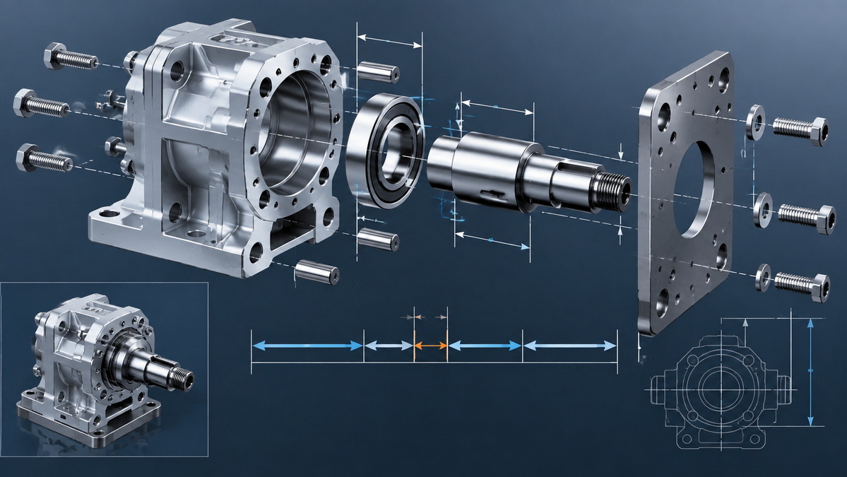
Imagine a sheet metal mounting plate attached to a machined aluminum housing with four screws.
The housing has threaded holes. The mounting plate has clearance holes. If the clearance holes are too small or positioned too tightly without considering the thread-hole location variation, assembly may become difficult.
The better approach is to:
1. Identify the housing mounting face as the primary reference.
2. Define the critical locating features.
3. Calculate the expected positional variation of threaded holes.
4. Select suitable clearance-hole diameters.
5. Apply a positional tolerance to the clearance holes.
6. Confirm the assembly works at worst-case conditions.
This method reduces assembly problems without requiring every hole and outer dimension to be machined to an unnecessarily narrow tolerance.
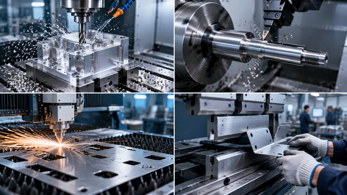
Each manufacturing process has its own strengths, limitations, and sources of variation.
A tolerance that is practical for CNC milling may be difficult for sheet metal bending. A tolerance that is reasonable for a precision-ground shaft may be unrealistic for a laser-cut profile. A dimension that is stable in a machined aluminum part may change after injection molding or heat treatment.
CNC machining is highly flexible and can achieve tight tolerances when the geometry, material, fixturing, and inspection method are appropriate.
Key considerations include:
- Tool reach and cutter deflection
- Part rigidity
- Wall thickness
- Depth-to-diameter ratio
- Fixture location
- Clamping force
- Machine thermal stability
- Tool wear
- Material stress relief
- Surface finish requirements
- Secondary operations
Long, thin, deep, or flexible features require special attention because they may deflect during machining or measurement.
Sheet metal fabrication involves different tolerance challenges.
Important considerations include:
- Material thickness variation
- Laser-cutting kerf
- Bend radius
- Bend angle
- Springback
- Forming tool wear
- Grain direction
- Flatness of incoming sheet
- Welding distortion
- Large-part handling
For sheet metal parts, engineers should identify the dimensions that matter after bending and use practical tolerances for non-critical formed areas.
Mold manufacturing requires high precision because the mold determines the shape and repeatability of the molded product.
However, the final molded component may still vary due to:
- Material shrinkage
- Fiber orientation
- Gate location
- Mold temperature
- Injection pressure
- Cooling rate
- Wall thickness variation
- Part geometry
- Post-molding conditioning
Engineers should distinguish between mold tolerances and final plastic-part tolerances. A highly accurate mold does not automatically guarantee the same dimensional result across every molded production cycle.
Stamping and cold forging can be highly efficient for volume production, but tooling, material behavior, and process direction significantly influence tolerances.
Key factors include:
- Die wear
- Punch-to-die clearance
- Material thickness
- Burr direction
- Springback
- Material hardness
- Grain flow
- Lubrication
- Tool alignment
- Secondary machining needs
Critical interfaces may require secondary CNC machining after stamping or forging. This hybrid approach can combine high-volume forming efficiency with precision control at selected features.
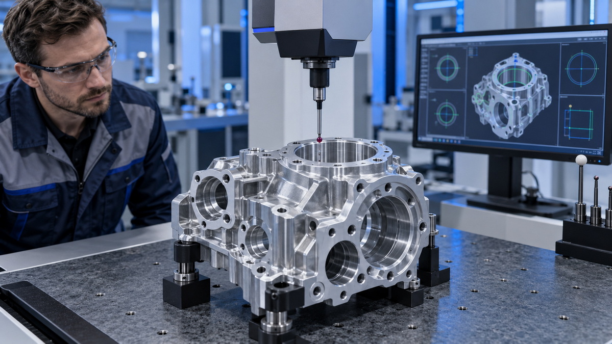
A tolerance requirement is only useful if it can be measured reliably.
For standard parts, calipers, tape measures, simple gauges, and visual checks may be sufficient. For high-tolerance CNC precision parts, more advanced inspection may be required.
- Digital calipers
- Outside micrometers
- Bore gauges
- Height gauges
- Pin gauges
- Plug gauges
- Ring gauges
- Thread gauges
- Surface roughness testers
- Optical measuring systems
- Coordinate measuring machines
- Air gauges
- Go/no-go gauges
- Profile projectors
The tighter the tolerance, the more important measurement uncertainty becomes.
If a tolerance range is extremely narrow, the measurement system must be capable of distinguishing acceptable parts from nonconforming parts with confidence.
For critical production components, an inspection plan may include:
- First article inspection
- Material certificates
- Dimensional inspection reports
- CMM reports
- Surface-finish verification
- Process capability review
- In-process inspection records
- Final inspection reports
- Lot traceability
- Packaging and handling requirements
Many production problems originate in drawings rather than on the shop floor.
Applying narrow tolerances to all dimensions increases cost and complexity without necessarily improving product performance.
Use tight control only where function requires it.
Without functional datums, inspectors and suppliers may measure the same part differently. This can create disagreements about whether a component is acceptable.
A part may look correct on its own but fail when installed with mating parts. Assembly-level analysis should guide tolerance decisions.
Plating, anodizing, painting, coating, heat treatment, polishing, and welding can change dimensions or surface conditions.
Critical dimensions should clearly state whether they apply before or after finishing.
A feature may be mathematically defined but difficult to inspect in a production environment. Engineers should consider inspection access when defining critical controls.
A supplier can manufacture more effectively when they understand why a feature matters.
For example, stating that a bore is a bearing seat or that a face is a sealing surface helps the manufacturing team prioritize the correct process, fixture, inspection method, and handling procedure.
U-Need works with global brands, distributors, manufacturers, and product-development teams that require dependable support from prototype development through production.
Our manufacturing services include:
- Custom CNC precision parts machining
- Injection mold manufacturing
- Stamping die manufacturing
- Cold-forging die manufacturing
- Sheet metal fabrication
- Laser cutting
- Metal bending
- Metal stamping
- Prototype manufacturing
- Low-volume and production-volume component supply
For high-tolerance CNC precision parts, the manufacturing review process can evaluate critical features, material behavior, datum selection, machining accessibility, fixture requirements, inspection strategy, surface finish, and post-processing effects.
For standard parts, the same review can identify opportunities to simplify machining, improve production efficiency, and reduce unnecessary specifications.
The most successful manufacturing drawings are not the most restrictive. They are the drawings that communicate the correct balance of functional accuracy, production repeatability, quality control, and commercial practicality.
High-tolerance CNC precision parts and standard parts both have important roles in modern product development and manufacturing.
High-tolerance parts are necessary when narrow variation directly affects fit, sealing, alignment, motion, safety, performance, or interchangeability. They require more sophisticated machining, fixturing, inspection, and process control.
Standard parts are suitable when broader variation does not compromise the final product. They can reduce manufacturing cost, shorten lead times, simplify inspection, and improve production efficiency.
The strongest engineering approach is to apply tight tolerances selectively. Engineers should identify critical-to-function features, establish functional datums, use geometric controls where necessary, perform tolerance stack-up analysis, account for material and process variation, and ensure that every critical requirement can be measured consistently.
For projects involving CNC machining, mold manufacturing, sheet metal fabrication, stamping, or cold forging, a practical tolerance review before production can help reduce risk, prevent costly design changes, and support more reliable product assembly.
A high-tolerance CNC precision part is a component with one or more features that must stay within a narrow allowable dimensional or geometric range. These parts are commonly used for bearing fits, sealing surfaces, precision mechanisms, medical devices, robotic systems, and aerospace components.
In most cases, yes. High-tolerance parts require more controlled machining, longer cycle times, advanced measurement equipment, more inspection, special tooling, and a higher level of process management. The cost increase depends on the material, geometry, production volume, and tolerance requirement.
General tolerances are useful for non-critical dimensions that do not affect assembly, sealing, alignment, safety, or product performance. They help simplify drawings and avoid applying unnecessary individual tolerances to every feature.
Datums establish the reference surfaces, axes, or points used to locate and inspect a part. A clear datum strategy helps manufacturers understand how the part functions in assembly and how critical features should be measured.
Tolerance stack-up analysis evaluates how dimensional variation from multiple components combines in an assembly. It helps engineers determine whether the assembled product will maintain sufficient clearance, alignment, fit, or functional performance under worst-case or expected production conditions.
Yes, but the tolerance strategy must account for sheet thickness, laser cutting, bend radius, springback, tool wear, forming sequence, welding distortion, and part size. Tight tolerances are usually best applied to critical datum-related features rather than every formed dimension.
Manufacturers may use micrometers, bore gauges, pin gauges, plug gauges, CMMs, optical measuring systems, air gauges, surface roughness testers, and custom go/no-go gauges. The inspection method should match the feature type and tolerance requirement.
1. American Society of Mechanical Engineers. [Dimensioning and Tolerancing: ASME Y14.5-2018 (R2024)]
2. American National Standards Institute. [ASME Y14.5-2018 (R2024): Dimensioning and Tolerancing]
3. International Organization for Standardization. [ISO 2768-1:1989—General Tolerances, Part 1]
4. National Institute of Standards and Technology. [Measurement Uncertainty Considerations for Coordinate Measuring Machines]
5. National Aeronautics and Space Administration. [System Engineering Toolbox for Design-Oriented Engineers]
6. U.S. Food and Drug Administration. [Process Validation: General Principles and Practices]


