Views: 243 Author: U-Need Publish Time: 2026-10-06 Origin: Site
Content Menu
● What Is Tight Tolerance CNC Machining?
>> Why Tight CNC Tolerances Are Difficult to Achieve
>> Common GD&T Controls Used in Precision Parts
● Tight Tolerance CNC Machining vs. GD&T Control
>> A Practical Example: Precision Mounting Plate
● The Features That Need the Most Attention
>> Mating Holes, Dowel Holes, and Fastener Patterns
>> Datum Surfaces and Mounting Faces
>> Bearing Seats, Bores, and Shaft Journals
>> Sealing Faces and Fluid Interfaces
>> Thin Walls, Deep Pockets, and Long Slender Features
● Why Over-Tolerancing Raises Cost
>> A Practical Tolerance Allocation Process
● Inspection Methods for Precision Parts
>> Tools for Dimensional Tolerance Inspection
● When to Use Tight Tolerances and GD&T Together
>> Example: Precision Motor Housing
● Precision Manufacturing Considerations for Different Processes
>> Injection Mold Manufacturing
>> Stamping Die and Cold-Forging Die Manufacturing
● Key Takeaways for Better Precision Parts
● FAQ
>> What is the main difference between tight tolerance CNC machining and GD&T control?
>> Is GD&T necessary for every CNC machined part?
>> What is considered a tight CNC machining tolerance?
>> Why is position tolerance important for hole patterns?
>> Why is flatness important for sealing surfaces?
>> Can tight tolerances increase manufacturing cost?
>> What information should be provided for a precision machining project?
Tight tolerance CNC machining and GD&T control are not competing methods. They work together to define whether a precision part will fit, align, seal, rotate, and perform as intended.
Tight tolerance CNC machining focuses on how closely an individual dimension must match its nominal value. GD&T control focuses on the allowable variation in a part's geometry and the functional relationship between its features. A diameter may be correct, for example, while the hole itself is misaligned, tilted, or located incorrectly relative to a mounting face.
For global manufacturers, distributors, and product developers, the most costly machining problems often come from unclear drawing requirements. Some drawings apply extremely tight ± tolerances to every feature but do not define the surfaces or axes that control assembly. Others include GD&T symbols but lack a practical datum strategy or inspection method.
The best approach is to identify the features that truly affect function, then use the right combination of dimensional tolerance, GD&T control, machining process, material selection, and inspection planning. This article compares tight tolerance CNC machining and GD&T control, explains which features need the closest attention, and provides practical guidance for designing more reliable custom precision parts.
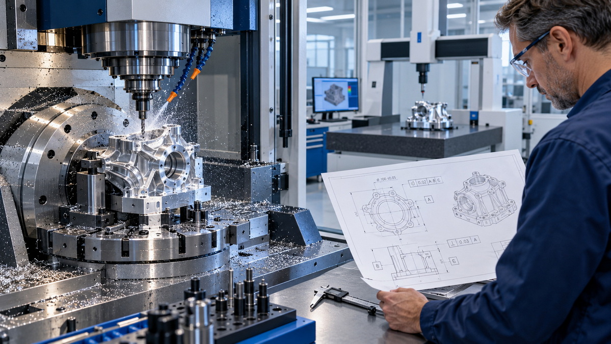
Tight tolerance CNC machining is the process of manufacturing a component within a narrow permitted variation from its specified nominal dimension.
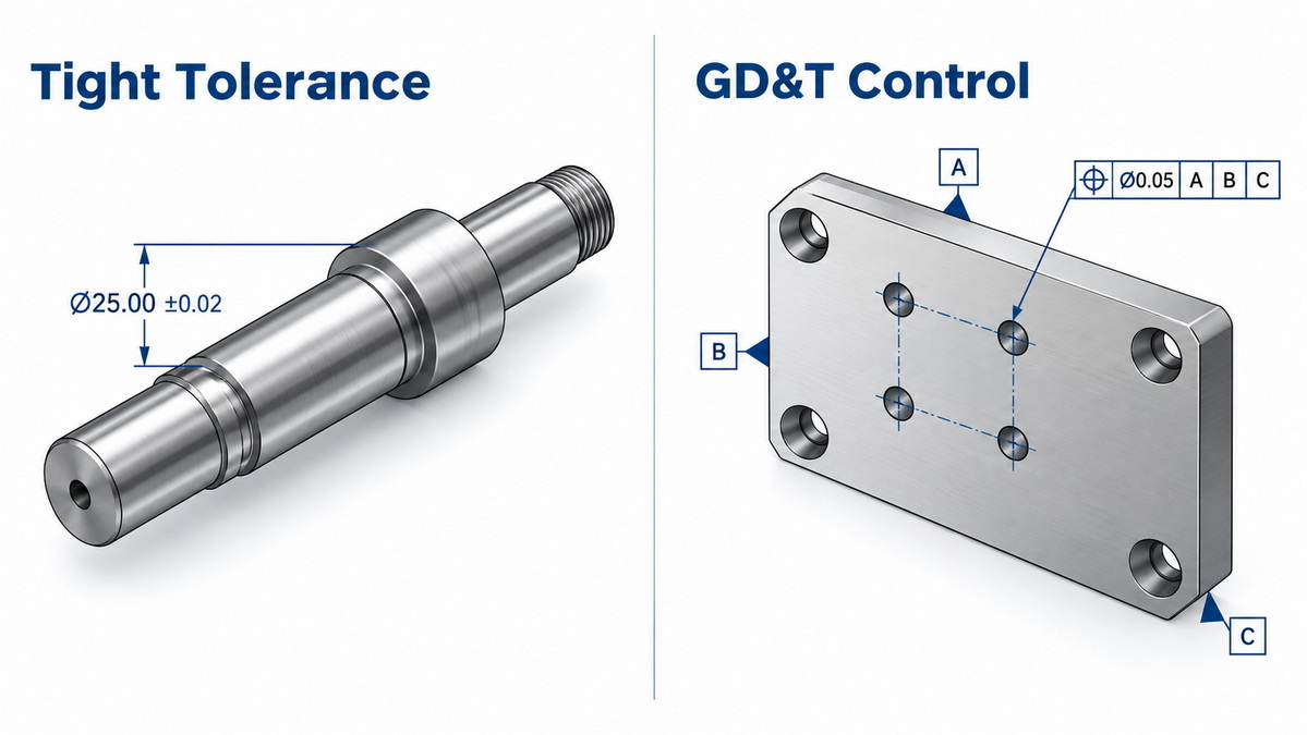
This means the finished shaft diameter must fall between 19.99 mm and 20.01 mm.
In practical machining, each dimension has an acceptable upper and lower limit. The smaller the allowable range, the more difficult the part becomes to produce consistently. Tight tolerances demand greater control over machine accuracy, cutting tools, workholding, material condition, temperature, inspection, and process stability.
A standard machined component may allow general variations around ±0.10 mm. A higher-precision feature may require ±0.025 mm. More demanding applications may need ±0.01 mm or tighter, especially for critical shafts, bearing fits, locating pins, optical components, medical devices, and precision mold parts.
However, a tighter tolerance does not automatically create a better part. It only adds value when the dimension directly influences fit, function, sealing, movement, alignment, or safety.
A narrow dimensional tolerance affects the entire manufacturing process, not just the final machining pass.
Important factors include:
- Machine capability: Axis accuracy, spindle condition, repeatability, thermal stability, and machine calibration all influence achievable tolerance.
- Workholding stability: Weak clamping, poor fixture design, or excessive clamping force can distort the workpiece.
- Tool deflection: Long tools, small-diameter cutters, deep pockets, and hard materials can cause cutting tools to flex during machining.
- Tool wear: A cutting edge changes over time. Even small wear can affect a precision dimension.
- Material stability: Aluminum, stainless steel, tool steel, titanium, plastics, and cast materials respond differently to cutting forces and temperature.
- Heat treatment movement: Parts can distort during stress relieving, hardening, tempering, anodizing, plating, or coating.
- Inspection accuracy: Measuring equipment must be more accurate than the tolerance being verified.
- Production repeatability: A prototype can sometimes be adjusted manually, but production parts must remain consistent across multiple batches.
For example, machining an aluminum plate to a general size tolerance may be straightforward. But holding the same plate to a tight thickness tolerance while also controlling flatness, parallelism, hole position, and surface finish requires more planning. The machining sequence, fixture design, finishing operations, inspection method, and material selection all become more important.
Geometric Dimensioning and Tolerancing, commonly called GD&T, is a symbolic language used on engineering drawings to define the allowable variation of a part's geometry.
Traditional dimensional tolerances describe the acceptable variation in size. GD&T goes further by describing the acceptable variation in shape, orientation, location, and rotational behavior.
GD&T helps manufacturers understand how features must relate to one another during actual assembly and use.
For instance, a drawing may state that a hole is 10 mm in diameter. This controls hole size. But the drawing may also need to control:
- How accurately the hole is located from the mounting edges
- Whether the hole axis is perpendicular to the mounting face
- Whether several holes align correctly as a pattern
- Whether the hole is concentric with a bearing bore
- Whether the hole remains within a functional location zone
- Whether the feature can be inspected consistently
Without these controls, a part may appear correct when measured feature by feature but still fail during assembly.
| GD&T Control | Primary Purpose | Common Applications |
|---|---|---|
| Flatness | Controls how flat a surface must be | Sealing faces, base plates, mold plates, mounting surfaces |
| Straightness | Controls deviation along a line or axis | Shafts, guide rails, long machined features |
| Perpendicularity | Controls 90-degree orientation relative to a datum | Drilled holes, mounting faces, brackets |
| Parallelism | Controls parallel orientation relative to a datum | Slide surfaces, plate faces, guide components |
| Position | Controls the true location of a feature | Hole patterns, dowel holes, fastener holes, connectors |
| Profile | Controls a complex surface shape and location | Curved housings, contoured components, formed parts |
| Circular Runout | Controls variation during rotation at one cross-section | Bearing journals, shafts, rotating components |
| Total Runout | Controls variation over an entire rotating surface | Precision spindles, long shafts, cylindrical sealing features |
GD&T is especially useful when a part must mate with another component. Rather than controlling every dimension independently, it defines how the critical features work together as a functional system.
The main difference is simple:
- Tight tolerance CNC machining controls how close an individual dimension must be to the target value.
- GD&T control defines how a feature must be shaped, located, oriented, or related to functional datums and other features.
Both may be required on the same part.
| Comparison Area | Tight Tolerance CNC Machining | GD&T Control |
|---|---|---|
| Main purpose | Controls dimensional size variation | Controls geometry and feature relationships |
| Typical notation | ±0.02 mm, limit dimension, unilateral tolerance | Feature control frame, symbols, datum references |
| Best suited for | Diameters, thicknesses, lengths, widths, clearances | Hole locations, mounting surfaces, shafts, profiles |
| Key benefit | Ensures a feature is manufactured near its intended size | Ensures features align and function correctly in assembly |
| Typical concern | Tight values can increase cost and production difficulty | Poor datum selection can create confusion or inspection problems |
| Common inspection tools | Micrometers, calipers, bore gauges, pin gauges, height gauges | CMMs, vision systems, functional gauges, granite surface plates |
| Effect on manufacturing cost | More precision usually means more setup time, machining time, and inspection | Can reduce unnecessary dimensioning when applied correctly |
| Most important question | "What size must this feature be?" | "How must this feature relate to the rest of the part?" |
Consider a CNC-machined mounting plate with four holes used to attach an electronic enclosure.
A conventional drawing may define each hole with separate X and Y dimensions:
- X = 30.00 ±0.05 mm
- Y = 20.00 ±0.05 mm
This appears accurate. However, the hole pattern may still shift enough to create assembly problems when the tolerances of all dimensions accumulate.
A more functional approach is to establish datum surfaces:
- Datum A: Primary mounting face
- Datum B: Long locating edge
- Datum C: Short locating edge
Then, apply a position tolerance to the hole pattern relative to those datums.
This method defines how the holes must relate to the surfaces that actually locate the part during assembly. It improves communication between design, machining, inspection, and assembly teams.
The result is often a part that is easier to inspect, more reliable in assembly, and more cost-effective to manufacture.
Not every feature deserves the same degree of precision. The most important features are those that affect fit, function, movement, location, sealing, electrical connection, load transfer, appearance, or repeatability.
Hole location is one of the most common sources of assembly failure. A hole may be the correct diameter but still be unusable if it is positioned incorrectly.
Critical hole features often include:
- Dowel pin holes used for repeatable positioning
- Bolt-hole patterns used to join housings, frames, covers, and brackets
- Threaded holes that must align with mating parts
- Bearing bores that must maintain location and orientation
- Connector openings that must align with electrical or mechanical interfaces
- Precision slots for adjustment or locating components
For these features, position tolerance is usually more meaningful than applying extremely tight coordinate dimensions independently.
A hole pattern should be evaluated based on how it functions in assembly. If the holes locate two components, their relationship to the functional datum surfaces matters more than their relationship to arbitrary drawing edges.
A datum is the reference used to locate and inspect other part features. In a functional assembly, it should reflect how the part is actually positioned.
Common datum features include:
- Base mounting surfaces
- Primary locating edges
- Bearing bore axes
- Sealing faces
- Guide rails
- Precision shoulders
- Mold plate surfaces
- Fixture contact surfaces
A poor datum strategy can make a drawing difficult to manufacture and inspect. It can also create conflict between the design intent and the production method.
For example, a mounting face may require flatness before a hole pattern can be measured accurately. If that face is warped, every feature located from it may appear to shift during inspection.
For mold components, datum planning is especially important. Mold plate flatness, guide pin alignment, insert location, shutoff surfaces, and cavity relationships can influence molding quality, flash control, parting-line appearance, and mold service life.
Rotating parts demand careful control because correct size alone does not guarantee smooth operation.
A bearing seat may need attention to:
- Diameter tolerance
- Roundness
- Cylindricity
- Surface roughness
- Bore position
- Axis alignment
- Perpendicularity of locating shoulders
- Circular runout
- Total runout
A shaft journal may meet its specified diameter but still cause vibration if it has excessive runout. A bearing bore may be on size but misaligned with another bore, resulting in binding, premature wear, noise, or difficult assembly.
For rotating equipment, total runout is often important because it evaluates the overall variation of the full rotating surface relative to a datum axis.
Sealing performance depends heavily on flatness, surface finish, and feature relationships.
Common examples include:
- Pump housings
- Valve bodies
- Hydraulic manifolds
- Battery enclosures
- Automotive covers
- Fluid control blocks
- Vacuum components
- Medical equipment housings
- Electronics enclosures with gasket seals
A sealing surface can meet its thickness specification and still leak if it is warped, uneven, scratched, or poorly finished.
When designing a sealing interface, consider:
- Flatness: Controls the overall shape of the sealing face
- Surface roughness: Supports proper contact with a gasket, O-ring, or metal seal
- Parallelism: Important when two opposing faces must clamp evenly
- Profile tolerance: Useful for complex sealing paths or irregular contours
- Corner radii: Prevents seal damage and improves manufacturability
- Fastener spacing: Affects clamping load distribution
A well-controlled sealing face protects product reliability and reduces the risk of field failures.
Thin walls and long features are challenging because they can bend, vibrate, or distort during machining.
Examples include:
- Thin-wall aerospace brackets
- Electronics housings
- Lightweight aluminum frames
- Deep-cavity mold inserts
- Long guide rails
- Slender shafts
- Precision pins
- Sheet metal enclosures with narrow flanges
A thin wall may be accurate while clamped but move after the part is released from the fixture. A deep cavity may have the correct opening size but taper internally because of tool deflection. A long shaft may have the correct diameter but fail straightness or runout requirements.
For these features, manufacturers should review:
- Material stiffness and internal stress
- Wall thickness and aspect ratio
- Fixture location and clamping force
- Roughing and finishing sequence
- Tool reach and cutter rigidity
- Machining direction
- Number of setups
- Need for stress relief
- Need for secondary finishing
- Accessibility for inspection
In some cases, changing the design slightly can reduce manufacturing risk significantly. Adding a support rib, increasing a wall thickness, adjusting an internal corner radius, or changing the datum strategy can improve yield without affecting product performance.

Over-tolerancing happens when dimensions or geometric requirements are tighter than the part's real functional needs.
It is one of the most frequent causes of unnecessary machining cost.
For example, a non-mating exterior edge may not need a ±0.01 mm tolerance. If that edge does not locate another part, create a seal, carry a bearing, or influence product performance, such a strict requirement may add cost without producing a practical benefit.
Tighter tolerances can lead to:
- More complex fixtures
- Longer machining cycles
- Slower finishing passes
- More frequent tool changes
- Higher inspection time
- More expensive measuring equipment
- Increased scrap risk
- Greater rework risk
- More secondary operations
- Longer production lead times
A general tolerance standard can be useful for non-critical features. This allows critical dimensions to receive individual attention while lower-risk features remain practical and cost-effective to manufacture.
Before releasing a drawing for prototype or production machining, follow a structured review process.
1. Identify the part's functional interfaces.
Determine which features assemble with other parts, transfer load, seal fluids, support rotation, locate components, carry electrical connections, or influence safety.
2. Define the datum scheme.
Select reference surfaces, axes, or features that reflect how the component will be located during assembly and inspection.
3. Control feature size where size is critical.
Use tight dimensional tolerances for press fits, bearing diameters, locating pins, interference fits, clearance holes, and critical wall thicknesses.
4. Control geometry where relationships are critical.
Use flatness, position, perpendicularity, parallelism, profile, and runout where feature relationships influence function.
5. Use general tolerances for non-critical dimensions.
Avoid applying overly strict values to dimensions that do not influence performance.
6. Check tolerance stack-up.
Review how variation accumulates across multiple parts, interfaces, fasteners, fixtures, and assemblies.
7. Match requirements to process capability.
Confirm that the selected material, machining process, tooling, workholding, finishing method, and inspection approach can achieve the desired result consistently.
8. Review inspection feasibility.
Ensure every critical requirement can be measured clearly, repeatably, and efficiently.
A clear tolerance strategy reduces uncertainty before machining begins. It also improves communication between engineering teams, purchasing teams, machinists, quality inspectors, and final assembly operators.
A precision drawing must be supported by a practical inspection plan.
The inspection method should be selected based on the part's tolerance level, geometry, material, quantity, and functional risk.
Common tools for verifying tight dimensions include:
- Digital calipers
- Outside micrometers
- Inside micrometers
- Bore gauges
- Plug gauges
- Pin gauges
- Thread gauges
- Height gauges
- Depth gauges
- Surface plates
- Go/no-go gauges
These tools are useful for straightforward dimensions such as diameters, thicknesses, depths, hole sizes, thread conditions, and basic linear measurements.
More complex geometric requirements often require advanced measurement systems, including:
- Coordinate measuring machines
- Optical measuring systems
- Vision inspection machines
- Portable measuring arms
- Dial indicators
- Roundness testers
- Surface roughness testers
- Functional inspection fixtures
- Granite surface plates
- Custom gauges
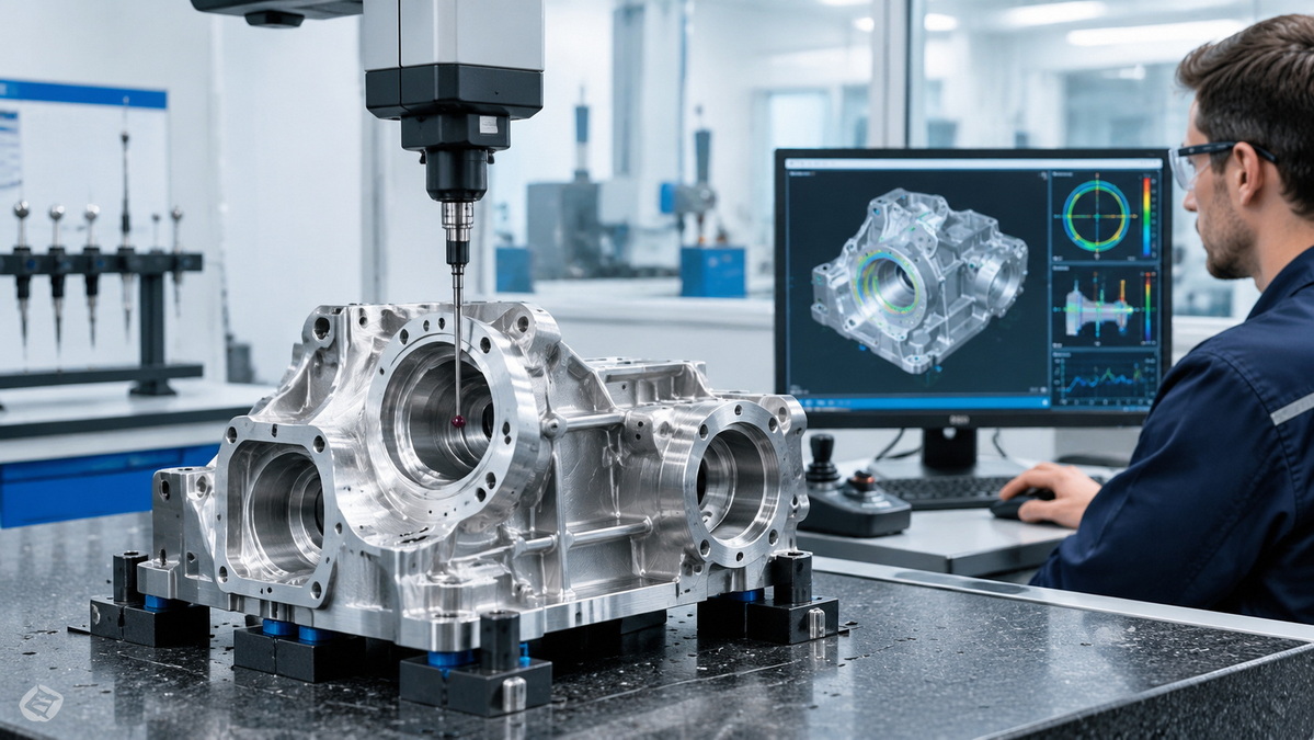
A coordinate measuring machine is especially useful for evaluating position, profile, perpendicularity, parallelism, complex hole patterns, and datum-based geometry.
However, inspection quality depends on more than equipment. The drawing must clearly identify datums, feature requirements, tolerance zones, and functional intent. Even advanced inspection systems cannot resolve unclear or conflicting technical requirements.
In many precision manufacturing projects, the correct answer is not choosing one method over the other. The answer is using both methods for the features that matter.
Use a tight dimensional tolerance when the physical size of a feature affects performance.
Use GD&T when the feature must also be accurately positioned, oriented, aligned, or controlled relative to other functional features.
A precision motor housing may require:
- A bearing bore diameter within a narrow tolerance range
- A controlled bore axis relative to the mounting face
- Perpendicularity between the bearing axis and the mounting face
- Flatness on the mounting flange
- Parallelism between opposing mounting surfaces
- Surface finish control on the bearing seat
- Accurate hole position for mounting fasteners
- Consistent thread depth for assembly screws
Each requirement protects a different aspect of the product.
The bore diameter controls bearing fit. The GD&T requirements control bearing alignment. The surface finish supports stable seating. The mounting face flatness supports proper assembly. The hole position ensures that the housing aligns with the mating structure.
This combination is particularly important in motors, gearboxes, pumps, valves, robotics, automation equipment, optical devices, industrial machinery, medical equipment, and high-performance consumer products.
Precision requirements do not apply only to CNC milling and turning. They also affect mold manufacturing, sheet metal fabrication, stamping, and forging tool production.
CNC milling, turning, drilling, tapping, grinding, and wire EDM can support highly precise features. The ideal process depends on part geometry, tolerance level, material, required finish, production quantity, and inspection requirements.
CNC machining is often suitable for:
- Precision housings
- Shafts and pins
- Bearing components
- Fixtures and jigs
- Tooling inserts
- Prototypes
- Automation components
- Medical parts
- Industrial equipment components
Mold components often require close control of cavity dimensions, insert locations, shutoff surfaces, guide systems, cooling channels, and mold plate relationships.
Critical areas may include:
- Cavity and core alignment
- Guide pin and bushing location
- Insert seating surfaces
- Slide and lifter movement
- Parting-line shutoff conditions
- Ejector pin position
- Cooling channel location
- Mold plate flatness
- Surface finish on cosmetic cavity surfaces
A small geometric error in a mold component can affect thousands or millions of molded parts.
Stamping dies and cold-forging dies require accuracy in die clearances, guide systems, punch alignment, working surfaces, and material flow paths.
Important features include:
- Punch-to-die alignment
- Die clearance
- Guide pillar position
- Working surface profile
- Die block flatness
- Insert fit
- Surface hardness
- Edge condition
- Repeatable locating features
The right tolerances improve tool life, part consistency, and production stability.
In sheet metal fabrication, the focus often shifts from individual dimensions to bend relationships, hole-to-bend distances, flatness after forming, and assembly alignment.
Important sheet metal features include:
- Bend angle
- Bend radius
- Hole position relative to bends
- Flange length
- Flatness of large panels
- Welding distortion
- Slot and tab alignment
- Fastener feature location
- Surface finish protection
A sheet metal part can be dimensionally correct in a flat state but shift after bending or welding. Therefore, functional datums and assembly requirements should guide the tolerance strategy.
The most successful custom precision parts start with a clear understanding of which features truly drive product performance.
Remember these principles:
- Tight tolerance CNC machining controls feature size.
- GD&T control manages shape, orientation, location, and feature relationships.
- A part can meet individual dimensions and still fail in assembly if geometric relationships are not controlled.
- Position tolerance is highly valuable for hole patterns, dowel holes, and locating features.
- Flatness, parallelism, and perpendicularity are critical for mounting faces, sealing surfaces, and precision assemblies.
- Runout and axis alignment matter for shafts, bearing seats, rotating components, and high-speed equipment.
- Thin walls, deep pockets, long shafts, and complex shapes require careful process planning.
- Over-tolerancing can increase cost, lead time, inspection effort, and scrap without improving performance.
- A functional datum strategy connects design intent with real manufacturing and inspection conditions.
- Early technical review helps prevent expensive problems before production begins.
For high-precision projects, the goal should not be to make every feature as tight as possible. The goal should be to make every important feature accurate enough to perform reliably, while keeping the part practical to manufacture and inspect.
U-Need supports global brands, distributors, and manufacturers with custom precision parts machining, mold manufacturing, sheet metal fabrication, laser cutting, bending, stamping, and related production solutions. A detailed review of drawings, materials, tolerances, surface requirements, and end-use conditions helps establish a manufacturing plan that supports both functional performance and stable production.
Tight tolerance CNC machining controls the allowable variation of an individual dimension, such as diameter, thickness, or length. GD&T control defines acceptable variation in geometry, including feature position, flatness, perpendicularity, parallelism, profile, and runout.
No. Simple parts with low functional risk may only need standard dimensional tolerances. GD&T becomes more important when a part must align with mating components, support bearings, create a seal, control rotating features, or meet strict assembly requirements.
The definition depends on the material, geometry, machining process, part size, inspection method, and production quantity. In many applications, ±0.10 mm may be a general machining tolerance, while ±0.025 mm or tighter is often considered a precision requirement.
Position tolerance controls the true location of holes relative to functional datums. This helps ensure that bolt holes, dowel holes, threaded holes, and connector holes align correctly with mating components during assembly.
A sealing surface can have the correct thickness but still leak if it is warped or uneven. Flatness control helps ensure consistent contact between the sealing surface and a gasket, O-ring, mating cover, or other sealing element.
Yes. Tight tolerances may require slower machining, more stable fixtures, more expensive tooling, extra finishing operations, additional inspection, and a higher level of process control. Tolerances should match actual functional needs.
A complete project package should include a 2D drawing, 3D CAD model, material specification, quantity, surface finish requirements, heat treatment details, coating requirements, tolerance requirements, GD&T callouts, inspection requirements, and information about the part's final application.
1. [ASME Y14.5 – Dimensioning and Tolerancing]
2. [NISTIR 4509: A Review of Current Geometric Tolerancing Theories and Inspection Practices]
3. [NIST Model-Based Enterprise and Product Manufacturing Information Resources]
4. [CNC Machining ISO-Based Tolerances and Finishes]
5. [CNC Machining Tolerances: Standard Machine and Guide]
6. [GD&T Professional Certification and ASME Y14.5]-geometric-dimensioning-and-tolerancing-professional-certification)


