Views: 219 Author: U-Need Publish Time: 2026-10-01 Origin: Site
Content Menu
● CNC Machining Tolerance and Part Function: What Is the Difference?
● Why Tight CNC Machining Tolerances Increase Cost
>> The Main Cost Drivers of Tight Tolerance Machining
● How Part Function Determines the Right Tolerance
>> Mating Fits and Assembly Clearance
>> Motion and Sliding Performance
● How Tight Is Tight Enough? A Functional Decision Process
>> Step 1: Identify Functional Features
>> Step 2: Define What Can Go Wrong
>> Step 3: Check Tolerance Stack-Up
>> Step 4: Choose the Correct Manufacturing Control
>> Step 5: Confirm Process Capability and Inspection Method
● Typical CNC Machining Tolerance Ranges
● Example: CNC-Machined Industrial Sensor Housing
● Common Tolerance Mistakes in Precision Manufacturing
>> Applying Tight Tolerances to Every Dimension
>> Forgetting Surface Treatments
>> Neglecting Inspection Planning
● How to Prepare a Better CNC Machining RFQ
● Work With a Function-Focused Manufacturing Partner
● FAQs
>> 1. What is considered a tight tolerance in CNC machining?
>> 2. Should every CNC-machined feature use a tight tolerance?
>> 3. What is the difference between dimensional tolerance and geometric tolerance?
>> 4. Why does a small tolerance increase the cost of CNC machining?
>> 5. Can anodizing, plating, or coating affect machining tolerances?
>> 6. How do I choose the right tolerance for a shaft and hole fit?
>> 7. When should I use grinding instead of CNC machining?
>> 8. Can U-Need review a drawing before production?
When a buyer requests a CNC-machined component, the first question is often about tolerance: Can the supplier hold ±0.01 mm? However, the more valuable question is: Does the part actually need ±0.01 mm to function correctly?
The relationship between CNC machining tolerance and part function affects product performance, assembly reliability, inspection requirements, production lead time, and total manufacturing cost. A tolerance that is too loose can create leakage, vibration, misalignment, poor fit, excessive wear, or assembly failure. A tolerance that is tighter than necessary can increase machining time, scrap risk, measurement cost, and the final price of the part.
For custom precision parts, the most effective approach is to define tolerances according to functional needs. This means applying tighter requirements only to the features that control fit, motion, sealing, load transfer, alignment, or critical appearance.
U-Need supports global brands, distributors, and manufacturers with custom precision parts machining, mold manufacturing, and sheet metal fabrication. From CNC-machined housings and shafts to injection mold components, stamping dies, and fabricated metal assemblies, the same principle applies: specify precision where it creates real functional value.
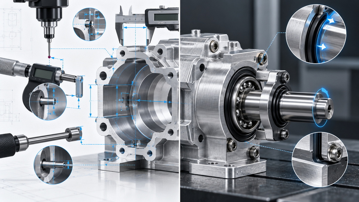
A CNC machining tolerance is the acceptable amount by which an actual manufactured dimension may differ from its nominal dimension.
A part function explains what that shaft must do in the final product. It may need to fit inside a bearing, rotate in a bushing, support a seal, transfer torque, locate another component, or slide through a guide.
The tolerance is the manufacturing limit. The function is the performance requirement.
| Aspect | CNC Machining Tolerance | Part Function |
|---|---|---|
| Main purpose | Controls acceptable dimensional variation | Defines how the part must perform in use |
| Typical drawing requirement | ± dimensions, limit dimensions, fit classes, geometric controls | Fit, sealing, movement, location, load support, assembly |
| Key question | How accurately must the feature be produced? | What must the feature achieve? |
| Main business impact | Affects process selection, inspection, and cost | Affects product quality, reliability, and usability |
| Best use | Apply a measurable production requirement | Define the reason behind the requirement |
A well-designed technical drawing connects these two elements. It does not simply demand the smallest possible tolerance. It explains which features matter and how they influence the final assembly.
Tighter tolerances require more than a high-quality CNC machine. They often require more process control at every manufacturing stage.
A dimension with a general tolerance may be completed through standard milling or turning. A dimension with a very tight tolerance may require multiple finish passes, special cutting tools, dedicated fixtures, controlled workholding, precision measuring equipment, or secondary operations such as grinding, honing, lapping, or wire EDM.
Longer cycle times.
Machinists may need to reduce cutting speed, take lighter finishing cuts, make multiple measurements, and perform additional tool compensation.
More complex setups.
A part that needs high concentricity, perpendicularity, or positional accuracy may require custom fixtures and fewer reclamping steps.
Higher inspection requirements.
Tight features may need micrometers, bore gauges, CMM inspection, optical measurement, air gauges, custom gauges, or complete inspection reports.
Greater scrap risk.
A part may perform correctly in assembly but fail inspection because a noncritical feature is slightly outside an unnecessarily strict tolerance.
Additional manufacturing processes.
Conventional CNC machining may not be the best choice for every ultra-precise feature. Grinding, EDM, honing, or lapping may become necessary.
More demanding environmental control.
Temperature changes can affect both the workpiece and the measuring equipment. For highly precise components, thermal stability can matter during machining and inspection.
The goal is not to avoid tight tolerances. The goal is to apply them with purpose.
> A tight tolerance is valuable when it protects part function. It becomes wasteful when it controls a feature that has no meaningful impact on performance.
The correct tolerance starts with a functional review of the part. Engineers should examine how the component interacts with mating parts, fasteners, seals, fluids, motion systems, tooling, loads, and real operating conditions.
Many CNC-machined parts must fit with another component. Common examples include shafts and bores, locating pins and pin holes, bushings and housings, bearings and bearing seats, gears and hubs, and threaded features.
The required tolerance depends on the intended fit.
| Fit Type | Functional Purpose | Typical Example |
|---|---|---|
| Clearance fit | Allows parts to assemble or move freely | Shaft moving through a guide bushing |
| Transition fit | Provides controlled location with limited play | Gear hub mounted on a shaft |
| Interference fit | Creates a secure press-fit connection | Bearing installed in a housing |
| Sliding fit | Allows repeatable movement with controlled clearance | Precision actuator guide |
| Locational fit | Positions components accurately during assembly | Dowel pin and fixture plate |
A tolerance should reflect the required fit condition, not simply an arbitrary tight number.
For example, a shaft for a sliding assembly needs enough clearance to prevent binding. However, excessive clearance may create vibration, noise, uneven wear, or poor positional repeatability. A bearing seat may need a more controlled fit to prevent bearing movement, but an overly tight fit can damage the bearing during assembly or create unwanted internal stress.
The right tolerance depends on how the two parts work together.
Sealing features often require close attention because leaks can cause product failure, reduced pressure, contamination, corrosion, or damage to electrical components.
Typical sealing features include:
- O-ring grooves
- Gasket contact surfaces
- Valve seats
- Hydraulic manifolds
- Pump housings
- Fluid channels
- Battery enclosure faces
- Connector interfaces
- Protective equipment housings
For sealing performance, dimensional tolerance is only one part of the requirement. The drawing may also need to define:
- Surface flatness
- Surface roughness
- Parallelism
- Groove width and depth
- Hole location relative to a sealing path
- Material condition
- Bolt-load distribution
- Surface treatment condition
A very tight overall dimension will not automatically prevent leakage. A sealing face can have the correct size but still fail if it lacks sufficient flatness or has an unsuitable surface finish.
For sealing surfaces, use the control that protects the seal itself.
Moving parts require a balance between clearance and control. This applies to shafts, pistons, plungers, guides, rails, sliding blocks, actuator components, bushings, and mechanical linkages.
A moving interface should account for more than room-temperature measurements. It should also consider:
- Thermal expansion
- Lubrication condition
- Dust or debris
- Coating thickness
- Surface finish
- Operating speed
- Misalignment
- Load-related deflection
- Wear over time
- Cleaning or maintenance conditions
For example, an aluminum housing and a steel shaft expand at different rates when temperature changes. A fit that feels smooth during prototype inspection may become tight in a hot operating environment or loose in a low-temperature environment.
When a part operates outdoors, near motors, inside industrial equipment, or in high-temperature systems, tolerance selection should reflect real working conditions rather than ideal inspection conditions.
Location accuracy becomes important when one feature must align with another feature or mating component.
Common examples include:
- Dowel pin holes
- Bearing bores
- Mounting-hole patterns
- Sensor bores
- Connector pockets
- Motor mounting faces
- Gearbox interfaces
- Valve passages
- Tooling alignment features
- Mold cavity inserts
For these applications, a standard plus/minus dimension may not fully explain the functional requirement.
A hole may have the correct diameter but still be in the wrong location. A bore may have the correct size but not be perpendicular to the mounting surface. A mounting pattern may meet individual coordinate limits but still fail to align with the mating component.
Geometric controls can communicate the relationship between functional features more clearly.
| Functional Requirement | More Effective Control |
|---|---|
| Hole pattern must align with a mating part | Position tolerance |
| Sealing surface must remain even | Flatness |
| Bore must be perpendicular to a mounting face | Perpendicularity |
| Rotating diameter must run smoothly | Runout |
| Complex outer surface must match design form | Profile |
| Two surfaces must remain evenly spaced | Parallelism |
| Critical feature must locate from a primary face | Datum reference |
The most useful drawing controls reflect the way the part is actually positioned and used in the assembly.
Before applying a highly restrictive tolerance, use a structured review process.
Start by identifying the surfaces and dimensions that directly influence performance.
These may include:
- Bearing seats
- Shaft journals
- Precision bores
- Dowel pin holes
- Threaded features
- O-ring grooves
- Sealing faces
- Gear mounting surfaces
- Alignment faces
- Connector interfaces
- Optical or sensor features
- Tooling and mold insert locations
Not every feature is functionally critical. External corners, clearance pockets, non-mating surfaces, and hidden profiles may be suitable for a general tolerance.
For each critical feature, identify the risk if the dimension varies too much.
| Feature | Risk If Too Loose | Risk If Too Tight |
|---|---|---|
| Bearing bore | Bearing movement, vibration, poor alignment | Difficult insertion, bearing distortion |
| Shaft diameter | Excessive play, noise, runout | Binding, high friction, seizure |
| O-ring groove | Insufficient compression, leakage | O-ring damage, excessive compression |
| Dowel hole | Poor location repeatability | Difficult pin insertion |
| Mounting-hole pattern | Assembly misalignment | Interference with mating fasteners |
| Sliding guide | Vibration, unstable movement | Binding and increased friction |
| Tooling insert pocket | Insert movement, flash, poor repeatability | Difficult installation or insert damage |
This process turns tolerance selection into a performance decision rather than a drawing habit.
A component is rarely evaluated by itself. It must work with mating parts, fasteners, fixtures, seals, coatings, and other production variations.
The minimum clearance identifies the tightest possible assembly condition. The maximum clearance identifies the loosest possible assembly condition.
In a more complex assembly, multiple tolerances can accumulate. A mounting plate, bracket, fastener hole, locating pin, housing bore, and sensor may each vary within specification. If those variations all shift in the same direction, the final assembly may fail even though every individual component meets its drawing.
Tolerance stack-up analysis is essential when assembly accuracy matters.
Different features need different types of requirements.
| Feature Type | Recommended Approach |
|---|---|
| Noncritical external dimensions | General tolerance |
| Shaft and bore fit | Limit dimensions or fit system |
| Hole alignment | Position control with functional datums |
| Sealing face | Flatness, surface finish, parallelism |
| Rotating diameter | Runout, cylindricity, surface finish |
| Precision pocket or contour | Profile control |
| Cosmetic visible surface | Visual standard and surface finish |
| Sheet metal bend relationship | Bend angle, flange position, formed profile |
Using the right control method can reduce unnecessary precision while improving clarity.
For example, a mounting hole pattern may not need extremely tight X and Y dimensions. It may be more useful to define the hole location relative to the part's actual mounting datums.
A drawing should match the intended manufacturing process and inspection plan.
Before production, verify:
- Can the selected machining process hold the specified tolerance?
- Is the material stable enough for the requirement?
- Does the part need a special fixture?
- Will heat treatment or coating affect the final dimension?
- Is the tolerance required before or after surface treatment?
- Can the feature be measured accurately?
- Is the measurement method repeatable?
- Is a first article inspection report required?
- Does the production volume justify a custom gauge?
A tolerance is only useful when it can be manufactured and verified consistently.
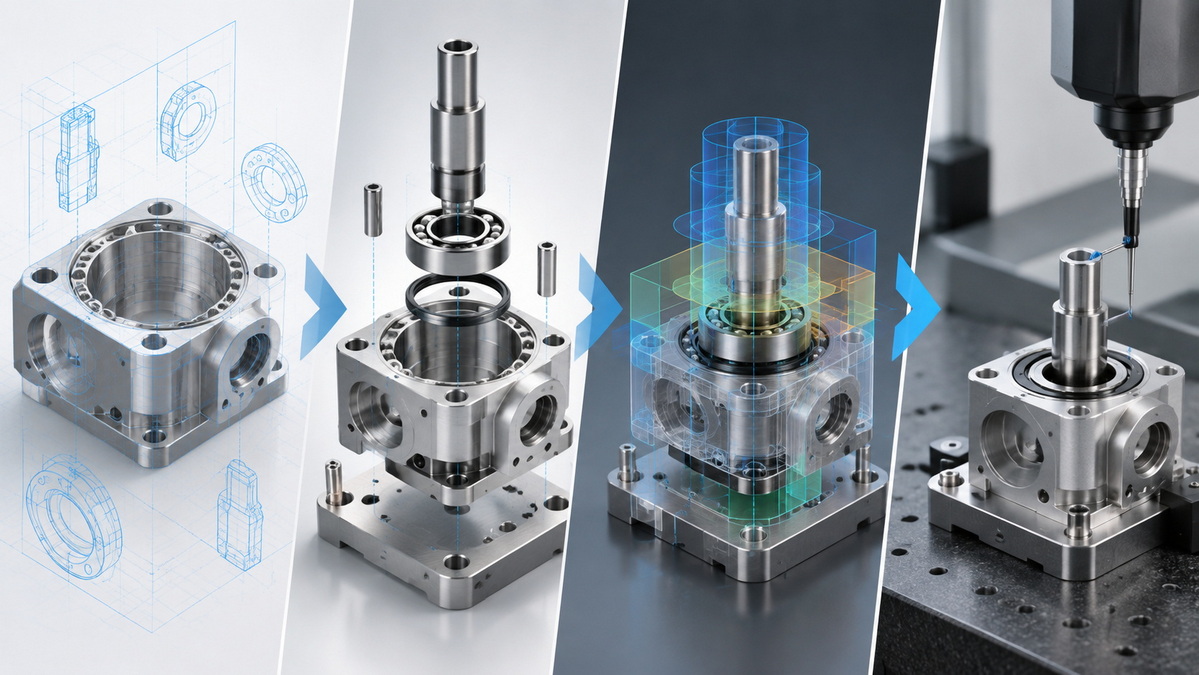
The capability of a manufacturing process depends on feature size, part geometry, material, machine condition, cutting strategy, workholding, inspection method, and production volume.
The following ranges are useful starting points for early design discussions.
| Manufacturing Process | Typical Tolerance Range | Common Applications |
|---|---|---|
| General CNC milling | ±0.05 mm to ±0.10 mm | Brackets, housings, general pockets and profiles |
| Precision CNC milling | ±0.01 mm to ±0.025 mm | Locating surfaces, precise pockets, mating features |
| General CNC turning | ±0.025 mm to ±0.05 mm | Standard shafts, threaded components, turned profiles |
| Precision CNC turning | ±0.005 mm to ±0.01 mm | Bearing journals, sealing diameters, precision shafts |
| CNC drilling | ±0.05 mm to ±0.10 mm | Clearance holes and general hole features |
| Reaming | ±0.005 mm to ±0.02 mm | Dowel holes, precision bores, controlled fit holes |
| Wire EDM | ±0.005 mm to ±0.01 mm | Tooling inserts, hard materials, precision profiles |
| Surface grinding | ±0.0025 mm to ±0.005 mm | Flat surfaces, hardened components, precision tooling |
| Cylindrical grinding | ±0.0025 mm to ±0.005 mm | Precision shafts, bearing seats, rotating features |
| Honing or lapping | ±0.001 mm to ±0.005 mm or finer | High-precision bores, sealing interfaces, special components |
These values are general references, not automatic production guarantees.
A small hardened steel bore, a thin-wall aluminum housing, and a long stainless-steel shaft may all require different methods to achieve the same numeric tolerance. It is important to review each feature in context.
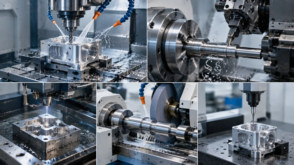
Consider an aluminum sensor housing used in automated equipment. The housing includes a mounting flange, four mounting holes, a precision sensor bore, a connector pocket, an O-ring sealing groove, and external cosmetic surfaces.
A drawing that applies ±0.01 mm to every dimension would create a costly and difficult manufacturing requirement. It would also make inspection more time-consuming without necessarily improving performance.
A function-based drawing would focus on the critical features.
| Feature | Main Functional Requirement | Appropriate Priority |
|---|---|---|
| Sensor bore | Holds sensor at the correct depth and orientation | Diameter, perpendicularity, surface finish |
| O-ring groove | Prevents dust and fluid ingress | Groove geometry, surface finish, sealing-face flatness |
| Mounting-hole pattern | Aligns housing with mating equipment | Position relative to mounting datums |
| Connector pocket | Allows reliable connector engagement | Profile and clearance |
| External faces | Supports product appearance | General dimensional control and cosmetic finish |
| Internal clearance pocket | Provides space for internal components | General tolerance unless it affects fit |
This method provides several benefits:
- The sensor is positioned accurately.
- The O-ring can seal correctly.
- The housing mounts reliably.
- The connector can engage without interference.
- Noncritical features remain economical to machine.
- Inspection focuses on the dimensions that affect performance.
The result is a more manufacturable part with better cost control and clearer quality expectations.
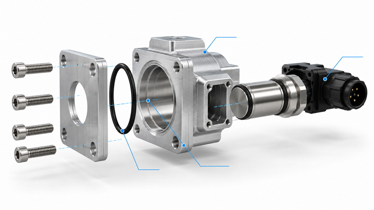
This is one of the most expensive drawing mistakes.
A tight tolerance should not be used as a general sign of quality. It should be reserved for dimensions that affect fit, function, safety, product appearance, or key assembly relationships.
Different materials respond differently to machining forces, heat, stress relief, plating, anodizing, welding, and environmental temperature changes.
Important material-related considerations include:
- Aluminum can move after material removal, particularly in thin-wall structures.
- Stainless steel can generate heat and work-harden during machining.
- Engineering plastics can absorb moisture or change dimension with temperature.
- Tool steel may change after heat treatment.
- Die-cast parts may contain variation that affects secondary machining.
- Sheet metal can spring back after bending.
Tolerance selection should reflect actual material behavior.
Surface treatments can change the final size of a feature.
Common treatments include:
- Anodizing
- Electroplating
- Powder coating
- Painting
- Passivation
- Heat treatment
- Black oxide
- PVD coating
- Electropolishing
A shaft, bore, thread, or sealing surface may fit correctly before finishing but fail after coating. Critical dimensions should clearly identify whether they are measured before or after the specified treatment.
Datums should reflect how the part is located in the real assembly.
For example, if a machined housing mounts against a flat base and locates from two dowel pins, those functional surfaces should guide the datum structure. Referencing unrelated external edges can create measurement results that do not match actual assembly performance.
A clear datum scheme helps both production and inspection teams understand the part's functional intent.
An ultra-tight tolerance is not useful if the supplier cannot inspect it accurately.
A reliable inspection plan may require:
- Calibrated micrometers
- Pin gauges
- Bore gauges
- Height gauges
- Thread gauges
- Optical measurement systems
- Coordinate measuring machines
- Surface roughness testers
- Custom go/no-go gauges
- Functional assembly gauges
For production parts, the inspection method should be agreed before manufacturing begins.
A complete RFQ helps suppliers understand the real requirements and provide a more accurate quotation.
Include the following information:
1. A current 2D drawing with dimensions, tolerances, datums, and revision control
2. A 3D CAD file in STEP, IGES, Parasolid, or another accepted format
3. Material grade, hardness, and approved alternatives
4. Surface finish and treatment requirements
5. Critical dimensions clearly identified
6. Mating-part information for fit, alignment, and sealing features
7. Expected annual quantity and prototype quantity
8. Required inspection documents
9. Packaging, labeling, and traceability needs
10. Target lead time and shipping destination
When possible, explain why a feature is critical.
For example, a note such as bearing seat, O-ring sealing surface, dowel location, sliding fit, or sensor alignment feature gives manufacturing engineers valuable context. It allows them to recommend a process that supports both performance and cost control.
The strongest precision manufacturing projects begin before the first chip is cut. A detailed drawing review can identify over-toleranced features, clarify functional datums, evaluate process capability, reduce unnecessary secondary operations, and establish an inspection plan that matches the part's real purpose.
U-Need provides end-to-end support for custom precision parts machining, mold manufacturing, injection molds, stamping dies, cold-forging dies, laser cutting, bending, stamping, and sheet metal fabrication. Our engineering team can review drawings and 3D files to help identify practical tolerance strategies for prototype, low-volume, and production projects.
Send your drawings, material requirements, mating-part details, surface treatment needs, and critical functional concerns to U-Need. A focused manufacturing review can help turn a complex tolerance specification into a practical, cost-effective production plan.
The correct CNC machining tolerance is not always the tightest tolerance. It is the one that allows the part to fit, move, seal, align, assemble, and perform as intended.
A function-based tolerance strategy helps manufacturers and buyers:
- Reduce unnecessary machining cost
- Improve production consistency
- Simplify inspection requirements
- Prevent assembly issues
- Protect critical interfaces
- Improve supplier communication
- Support reliable performance from prototype through mass production
When tolerance requirements are linked directly to part function, every micron has a purpose. That approach creates clearer drawings, stronger parts, better production decisions, and more predictable results.
There is no single definition because machining difficulty depends on part size, material, geometry, workholding, and inspection method. In many projects, ±0.05 mm is suitable for general CNC machining, while ±0.01 mm or tighter is often considered a precision requirement.
No. Tight tolerances should be applied only to features that affect fit, motion, sealing, alignment, load transfer, product appearance, or safety. General tolerances are usually more suitable for noncritical surfaces and clearance features.
Dimensional tolerance controls size, such as diameter, length, width, or thickness. Geometric tolerance controls feature form, orientation, location, or runout. Examples include flatness, position, perpendicularity, parallelism, and profile.
Small tolerances can require slower machining, additional finishing passes, more stable fixtures, special cutting tools, precision inspection, higher scrap allowances, and secondary processes such as grinding or EDM. These requirements increase both cycle time and quality-control cost.
Yes. Surface treatment can change feature size, surface condition, and fit. Critical dimensions should state whether they apply before or after finishing. This is especially important for shafts, bores, threads, bearing seats, and sealing surfaces.
Start with the required assembly condition. Consider whether the parts need clearance, controlled sliding movement, accurate location, or an interference fit. Also consider material, temperature changes, surface finish, lubrication, load, and installation method.
Grinding is often used when a part requires very tight size control, excellent surface finish, roundness, flatness, or performance on hardened material. It is commonly used for bearing seats, precision shafts, tooling components, and high-accuracy sealing or sliding surfaces.
Yes. U-Need can review part drawings and CAD files for manufacturability, machining process selection, tolerance practicality, material suitability, surface treatment effects, inspection requirements, and potential cost-saving improvements before prototype or production manufacturing.
1. National Institute of Standards and Technology. *Geometric Dimensioning and Tolerancing for Digital Manufacturing.*
[https://tsapps.nist.gov/publication/get_pdf.cfm?pub_id=936463]
2. National Institute of Standards and Technology. *Precision in Machining: Research Challenges.*
[https://nvlpubs.nist.gov/nistpubs/Legacy/IR/nistir5628.pdf]
3. National Institute of Standards and Technology. *Investigating the Role of Geometric Dimensioning and Tolerancing in Tolerance Specification.*
[https://tsapps.nist.gov/publication/get_pdf.cfm?pub_id=918538]
4. National Institute of Standards and Technology. *End-to-End Quality Information Framework Technology Survey.*
[https://nvlpubs.nist.gov/nistpubs/ir/2016/NIST.IR.8127.pdf]
5. NASA. *NASA-STD-5017B: Design and Development Requirements for Mechanisms.*
6. International Organization for Standardization. *ISO 286-1: Geometrical Product Specifications—ISO Code System for Tolerances on Linear Sizes.*
[https://www.iso.org/standard/54913.html]
7. American Society of Mechanical Engineers. *ASME Y14.5 Dimensioning and Tolerancing.*
[https://www.asme.org/codes-standards/find-codes-standards/y14-5-dimensioning-tolerancing]


