Views: 245 Author: U-Need Publish Time: 2026-08-24 Origin: Site
Content Menu
● CNC Fixture vs. Jig: What Is the Difference?
● Why CNC Fixtures Matter in Precision Manufacturing
>> Key Benefits of CNC Workholding Fixtures
● The 3-2-1 Locating Principle
>> Why Over-Constraining a Part Can Cause Errors
>> Fixtures by Machining Operation
>> Fixtures by Production Requirement
● How to Select the Right CNC Fixture
>> Questions to Review Before Fixture Design
>> Workholding Recommendations by Part Type
● Practical CNC Fixture Design Rules
>> Use Controlled Clamping Force
● Advanced Workholding Options
>> Pneumatic and Hydraulic Fixtures
>> Zero-Point and Quick-Change Systems
● U-Need's Precision Manufacturing Approach
● Build a More Stable CNC Machining Process
● FAQ
>> What is the difference between a fixture and a jig?
>> What is the 3-2-1 locating principle?
>> When is a custom CNC fixture needed?
>> Can too much clamp force affect machining accuracy?
>> Are vacuum fixtures suitable for every part?
>> How can a fixture reduce CNC machining cost?
A CNC fixture is a purpose-built workholding system that locates, supports, and secures a workpiece during machining. It helps manufacturers achieve stable cutting conditions, repeatable positioning, reliable dimensional accuracy, and more efficient production.
For global brands, distributors, and manufacturers sourcing precision parts from China, the right CNC fixture design can influence part quality, scrap rates, setup time, throughput, and total manufacturing cost. At U-Need, fixture planning is considered alongside part geometry, machining methods, material properties, tolerance requirements, and production volume.
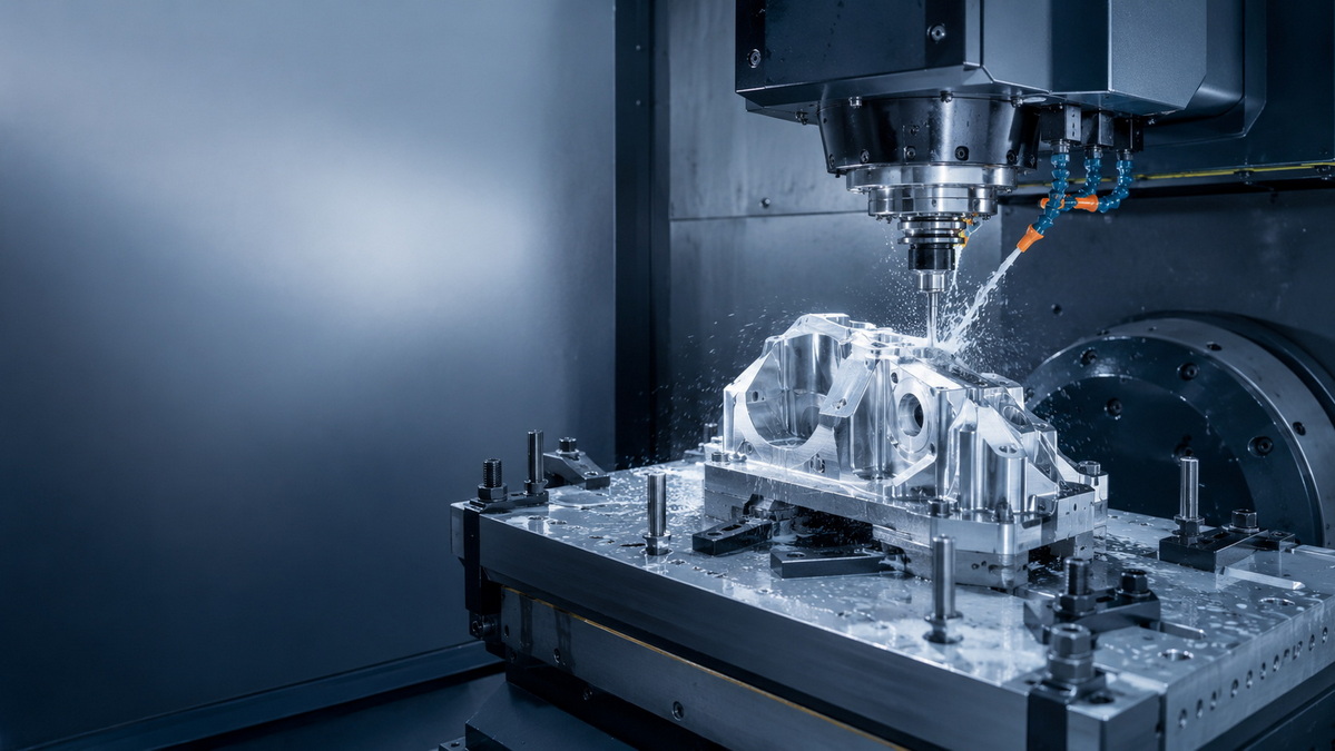
A CNC fixture is a workholding device designed to position, support, and clamp a part in a defined orientation during machining. It prevents the workpiece from moving under cutting forces while maintaining access to the surfaces and features that need to be machined.
Unlike a standard vise, chuck, or clamp, a custom fixture is designed around a specific part. It may be developed for a single component, a family of similar components, or a recurring production program.
A reliable fixture performs three essential tasks:
- Locating: Establishing the correct part position in relation to the machine coordinate system.
- Supporting: Preventing vibration, bending, or deflection during machining.
- Clamping: Holding the part against its locating surfaces without damaging or distorting it.
A part can be clamped tightly and still be machined inaccurately. Poor datum selection, uneven support, excessive clamp force, or limited tool access can all create variation. Effective fixture design balances rigidity, accessibility, repeatability, loading speed, and protection of finished surfaces.
The words "jig" and "fixture" are often used together, but they serve different purposes.
| Feature | CNC Fixture | Jig |
|---|---|---|
| Primary function | Locates, supports, and clamps the workpiece | Locates the workpiece and guides the cutting tool |
| Tool guidance | Does not guide the cutter | Often includes drill bushings or guide elements |
| Typical use | Milling, turning, grinding, drilling, and multi-axis machining | Repetitive drilling, reaming, and tapping |
| Main design priority | Rigidity, repeatability, tool access, and stability | Accurate tool guidance and hole location |
| Example | A fixture plate for 5-axis machining | A drill jig with hardened guide bushings |
In CNC operations, fixtures are commonly used because machine programs control tool movement. The fixture ensures that every workpiece enters the machining process in the same position.
A CNC fixture is not simply an accessory. It is a process-control tool that helps transform capable equipment into a consistent production system.
The value of a dedicated fixture becomes especially clear when a component has tight tolerances, complex geometry, thin walls, multiple machining operations, or repeat-order demand.
- Improved repeatability: Every workpiece is positioned against the same locating points.
- Higher dimensional consistency: Stable support and controlled clamping reduce variation.
- Faster setup: Operators can load a prepared fixture instead of manually indicating every part.
- Higher output: Multi-part fixtures can increase the number of components machined per cycle.
- Less operator dependency: A standardized fixture reduces differences in loading methods.
- Better machining stability: Proper support helps reduce vibration and tool chatter.
- Lower scrap risk: Reliable holding reduces part movement, deformation, and rework.
- Easier automation: Pneumatic, hydraulic, vacuum, and quick-change systems can reduce non-cutting time.
For example, a thin aluminum enclosure can flex if it is clamped only along its outside edges. A dedicated fixture can support the internal floor, spread the clamp force, and preserve flatness while leaving sufficient access for pocketing, drilling, and contour machining.
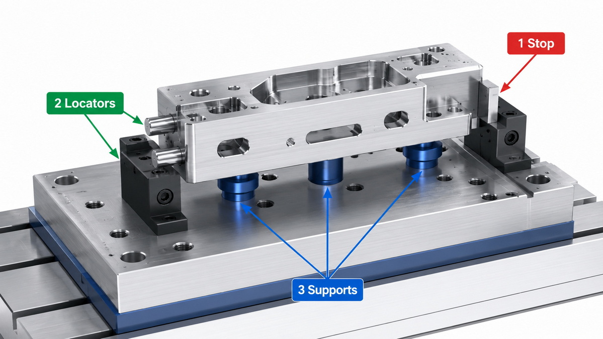
The 3-2-1 locating principle is a core method used to position a workpiece consistently. It controls the six possible movements of a rigid part: movement along three axes and rotation around those axes.
The method uses six locating contacts:
1. Three points establish the primary datum plane.
2. Two points establish the secondary datum plane.
3. One point establishes the tertiary datum plane.
These contacts position the workpiece in a stable and repeatable orientation. The primary plane normally supports the part from below. Secondary and tertiary locators control its side-to-side and end-to-end position.
| Locator Group | Main Purpose | Movement Controlled |
|---|---|---|
| Three primary supports | Establish the base datum surface | Vertical movement and two rotations |
| Two secondary locators | Define side orientation | One lateral movement and one rotation |
| One tertiary locator | Define final end position | Remaining lateral movement |
| Clamping components | Hold the part against locators | Resistance to machining forces |
The goal is not to add as many pins and clamps as possible. The goal is to provide enough control for accuracy while avoiding unnecessary constraint.
Extra locator pins can make a fixture less reliable. Real parts have small variations in size, flatness, and surface condition. When too many fixed locator points are used, the part may sit unevenly, become stressed during loading, or fail to seat consistently.
A better solution is to identify functional datums from the engineering drawing and build the locating strategy around them. Adjustable supports, spring-loaded rests, or compliant elements may be useful when the part has natural variation or thin-wall features.
CNC fixtures can be classified by machining process, level of customization, holding method, and production requirement.
- CNC milling fixtures: Used for face milling, pocketing, drilling, contouring, and multi-axis machining.
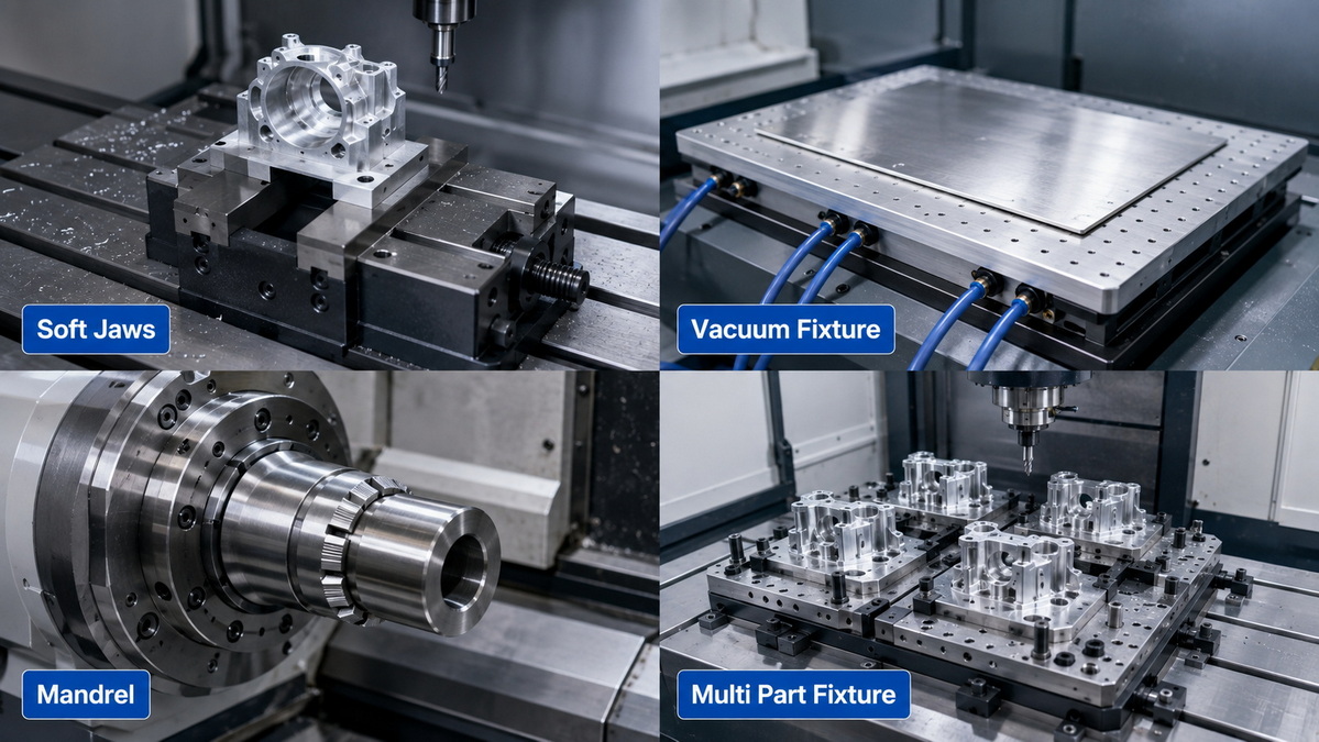
- CNC turning fixtures: Include chucks, collets, soft jaws, mandrels, and expanding arbors for shafts, rings, and rotational parts.
- Drilling fixtures: Position parts for repeated and accurate hole-making operations.
- Boring fixtures: Support components during precision enlargement or finishing of existing holes.
- Grinding fixtures: Hold parts securely during surface, cylindrical, or profile grinding.
- 5-axis fixtures: Provide access to several faces while reducing the need for multiple setups.
| Fixture Type | Suitable Applications | Advantage | Limitation |
|---|---|---|---|
| Universal fixture | Prototypes and simple components | Flexible and readily available | Less optimized for a specific part |
| Modular fixture | Low- to medium-volume production | Reusable and configurable | Can require more setup planning |
| Dedicated fixture | Repeated production of one component | Fast loading and high repeatability | Requires initial engineering and tooling investment |
| Multi-part fixture | Medium- to high-volume orders | Machines more parts per cycle | Needs careful chip removal and tool-access planning |
| Combination fixture | Families of similar components | Balances flexibility and productivity | May not provide ideal support for every version |
For prototype production, a standard vise, clamps, or machined soft jaws may be the most practical approach. For a repeat production component with multiple operations, a dedicated fixture can reduce labor time and create a more predictable process.
Fixture selection should begin with the part's engineering and production requirements. Starting with a preferred clamping method can lead to hidden issues, including slow setup, part damage, inconsistent tolerances, and difficult inspection.
- What dimensions and geometric tolerances are most critical?
- Which drawing datums are functional in final assembly?
- Which surfaces cannot have clamp marks?
- Is the part rigid, hollow, thin-walled, flexible, or vibration-sensitive?
- Which faces must remain accessible in the current setup?
- What machining forces will be applied?
- Is the material likely to deform under clamping pressure?
- What is the expected annual or monthly production volume?
- Can several components be machined safely in one cycle?
- How will chips, coolant, and burrs be removed?
- How can the operator confirm correct part orientation before machining?
| Part Condition | Suitable Fixture Direction |
|---|---|
| Flat, rigid prismatic part | Vise, fixture plate, toe clamps, or soft jaws |
| Cylindrical shaft, sleeve, or ring | Chuck, collet, mandrel, or expanding arbor |
| Thin plate or sheet-like machined part | Vacuum fixture, distributed supports, or low-force clamps |
| Complex multi-face component | Dedicated fixture with minimal tool obstruction |
| Repeat high-volume component | Hydraulic, pneumatic, or quick-change fixture |
| Part with cosmetic surfaces | Soft jaws, protected contact points, or non-marring clamping |
A productive fixture should make machining stable while keeping the operator's job straightforward.
Fixture locating surfaces should match the datums that matter for assembly, inspection, or performance. This creates a clearer relationship between part setup, machining results, and quality verification.
Avoid locating from rough, unstable, or non-functional surfaces unless the machining sequence requires it.
The clamping force should press the part toward its locating points. This keeps the workpiece seated correctly during machining.
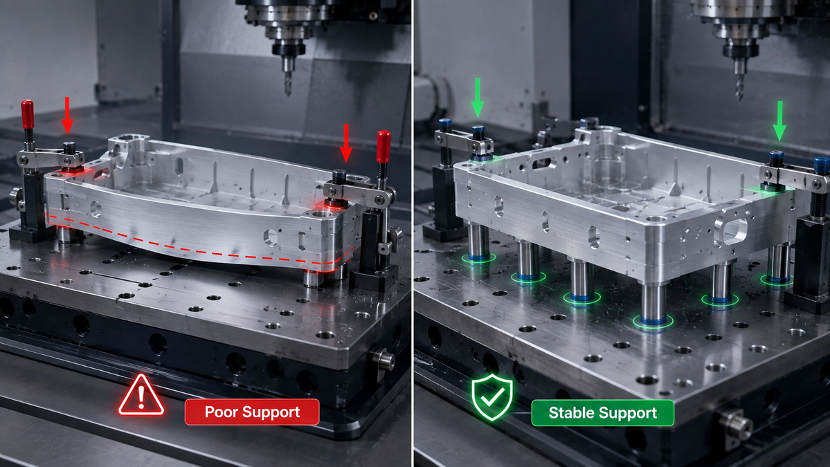
Clamps should normally act above supported areas. When a clamp presses on an unsupported thin wall, the part may bend during machining and spring back after it is released.
Excessive force can deform aluminum, stainless steel, plastics, thin-wall castings, and delicate machined components. The part may appear correct while clamped but fall outside tolerance after unclamping.
Use enough clamping force to resist machining loads, but avoid unnecessary pressure. Wider contact pads, soft jaws, multiple low-force clamps, and support points can protect sensitive components.
A fixture must secure the workpiece without blocking the cutter path. During fixture review, consider tool length, holder clearance, spindle access, machine travel, required machining angles, and potential collision zones.
This is particularly important for 4-axis and 5-axis machining, where poor fixture layout can limit access to critical features.
A fixture should be easy to load accurately. Add lead-in chamfers, clear stops, accessible clamps, and orientation-control features where possible.
A strong fixture design makes incorrect loading difficult. This can reduce setup variation and prevent avoidable machining errors.
Chips, coolant residue, burrs, and dust can prevent a part from seating correctly on its datum surfaces. Even a small chip under a workpiece can create a measurable positioning error.
Use open channels, drainage areas, accessible locator pins, and easy-to-clean surfaces. Operators should be able to inspect and clean critical locating points quickly between cycles.
Production requirements may justify more advanced fixture systems that reduce non-cutting time and improve consistency.
Pneumatic and hydraulic fixtures use controlled air or fluid pressure to apply repeatable clamping force. They can reduce manual effort and speed up part loading in repeat production.
Pneumatic systems are often suitable for faster, moderate-force clamping. Hydraulic systems can provide greater force where heavier cutting conditions or larger workpieces are involved.
Vacuum fixtures are useful for flat parts, panels, thin plates, and components that could be marked or distorted by mechanical clamps. They distribute holding force across a broader surface area.
Their suitability depends on the sealing surface, part size, material condition, cutting force, and available support. Vacuum holding should be evaluated carefully for aggressive milling operations.
Magnetic fixtures can hold ferrous materials during grinding and selected machining operations. They are not suitable for aluminum, brass, copper, titanium, plastics, or other non-ferromagnetic materials.
Zero-point systems allow fixtures to be removed and returned to the machine with repeatable positioning. They support offline setup preparation, faster fixture changes, and more flexible machine utilization.
Most fixture-related machining issues can be prevented through early planning and first-article validation.
- Using clamps without stable locating surfaces
- Clamping directly on unsupported thin sections
- Applying excessive clamping force
- Blocking access to critical machined features
- Using too many fixed locator points
- Ignoring chip evacuation
- Selecting a fixture without considering production volume
- Failing to protect cosmetic or finished surfaces
- Creating a loading process that depends too heavily on operator judgment
- Skipping repeated setup and inspection trials
A fixture should be validated through controlled trial machining. This process should include part loading checks, machining trials, critical-dimension inspection, clamp-mark review, repeated setup evaluation, and confirmation that the fixture remains stable over multiple cycles.
U-Need supports global brands, distributors, and manufacturers with integrated precision manufacturing capabilities in China. Our services include custom precision parts machining, mold manufacturing, injection molds, stamping dies, cold-forging dies, laser cutting, bending, stamping, and sheet metal fabrication.
For CNC machining projects, our engineers review part geometry, material selection, tolerance requirements, finishing specifications, machining sequence, production volume, and workholding needs. This allows the manufacturing plan to be developed around real production conditions rather than isolated part features.
Our typical project process includes:
1. Design and manufacturability review: Review 2D drawings, 3D models, materials, tolerances, and functional requirements.
2. Process planning: Define machining operations, setups, tools, inspection points, and production controls.
3. Fixture concept development: Select locating datums, support points, clamp directions, and loading methods.
4. Fixture and tooling production: Manufacture fixture plates, custom jaws, locator components, and dedicated workholding tools.
5. First-article machining: Produce and inspect sample parts before full production.
6. Ongoing production control: Monitor part consistency, fixture wear, loading reliability, and process stability.
The right fixture can support more than accurate machining. It can create a smoother production flow, reduce unnecessary handling, protect part surfaces, and make repeat manufacturing more reliable.
If a part shows tolerance variation, vibration, clamp marks, excessive setup time, or recurring scrap, the workholding method may be a major factor.
U-Need helps customers evaluate fixture requirements as part of the wider manufacturing process. By reviewing drawings, material specifications, part quantities, critical tolerances, and machining requirements early, engineering teams can identify a workholding approach that supports both quality and production efficiency.
A CNC fixture is a workholding device that locates, supports, and clamps a workpiece during machining. Its purpose is to keep the part stable, accurately positioned, and accessible to cutting tools.
A fixture holds and positions the workpiece. A jig both positions the workpiece and guides the cutting tool. CNC fixtures are commonly used because the machine program controls cutting-tool movement.
The 3-2-1 locating principle uses three points to establish a primary plane, two points to establish a secondary plane, and one point to establish a tertiary plane. Together, these points control the workpiece's position and orientation.
A custom fixture is useful when a part has tight tolerances, complex geometry, thin-wall sections, multiple machining operations, recurring production demand, or a requirement for faster and more repeatable setups.
Yes. Excessive clamp force can bend or compress a part during machining. When the clamp is released, the part can spring back and fall outside tolerance. This is especially common with thin-wall aluminum, stainless steel, plastics, and flexible components.
No. Vacuum fixtures are generally most suitable for flat parts with adequate sealing area and manageable cutting forces. They may not be appropriate for porous materials, small components, uneven surfaces, or heavy cutting conditions.
A fixture can reduce cost by shortening setup time, improving repeatability, allowing multi-part machining, reducing scrap, minimizing rework, and lowering dependence on manual positioning.
1. RapidDirect. [An Ultimate Guide to Understanding a CNC Fixture].
2. Carr Lane Manufacturing. [Locating and Clamping Principles for Jig and Fixture Design].
3. Reid Supply. [CNC Workholding Basics].
4. JLC CNC. [CNC Workholding Guide: Fixtures, Methods & Best Practices].
5. RivCut. [Fixture Design Principles: 3-2-1 Locating + Datums].
6. Ace Micromatic Group. [CNC Workholding Methods and Fixtures Guide].


