Views: 244 Author: U-Need Publish Time: 2026-11-17 Origin: Site
Content Menu
● What Is CNC Machining, and How Does It Differ From NC?
● The Origins of CNC Machining: Why Aerospace Needed Numerical Control
>> Manual Machining Created a Complex-Geometry Challenge
>> John T. Parsons and Frank L. Stulen Advanced the Idea
● The 1952 MIT Milling Machine: A Defining Historical Milestone
● CNC Machining History Timeline: Major Stages of Development
● How Computers and Digital Programming Changed Machining
>> Computerized Controllers Made Programs More Adaptable
>> CAD and CAM Connected Geometry With Toolpaths
>> Multi-Axis Machining Expanded Geometric Access
● What CNC History Teaches Buyers About Precision
>> 1. Design Intent Must Be Unambiguous
>> 2. The Process Must Control Variation
>> 3. Inspection Must Match the Requirement
● Practical Example: Planning a Precision Housing
● The Latest Direction: Connected Machines and Digital Twins
● A Buyer's Checklist for Choosing a Manufacturing Partner
● From CNC History to Your Next Manufacturing Project
● Frequently Asked Questions About CNC Machining History
>> Who invented CNC machining?
>> When was the first NC milling machine demonstrated?
>> What is the main difference between NC and CNC?
>> Why was aerospace important to CNC development?
>> Does CNC machining automatically guarantee precision?
>> How does CNC machining support mold manufacturing?
CNC machining history explains how manufacturing moved from manually guided cutting tools to programmable systems capable of producing complex, repeatable parts. Its foundations emerged in the 1940s, followed by a landmark numerical-control demonstration at MIT in 1952. Computerized controllers developed later, creating the technology manufacturers use today.
For engineers and buyers, this history offers more than interesting dates. It explains why digital designs, controlled toolpaths, reliable workholding, and inspection must work together.
At U-Need, we view precision manufacturing through that complete process: translating product requirements into a suitable manufacturing route, rather than treating a machine specification as a quality guarantee.
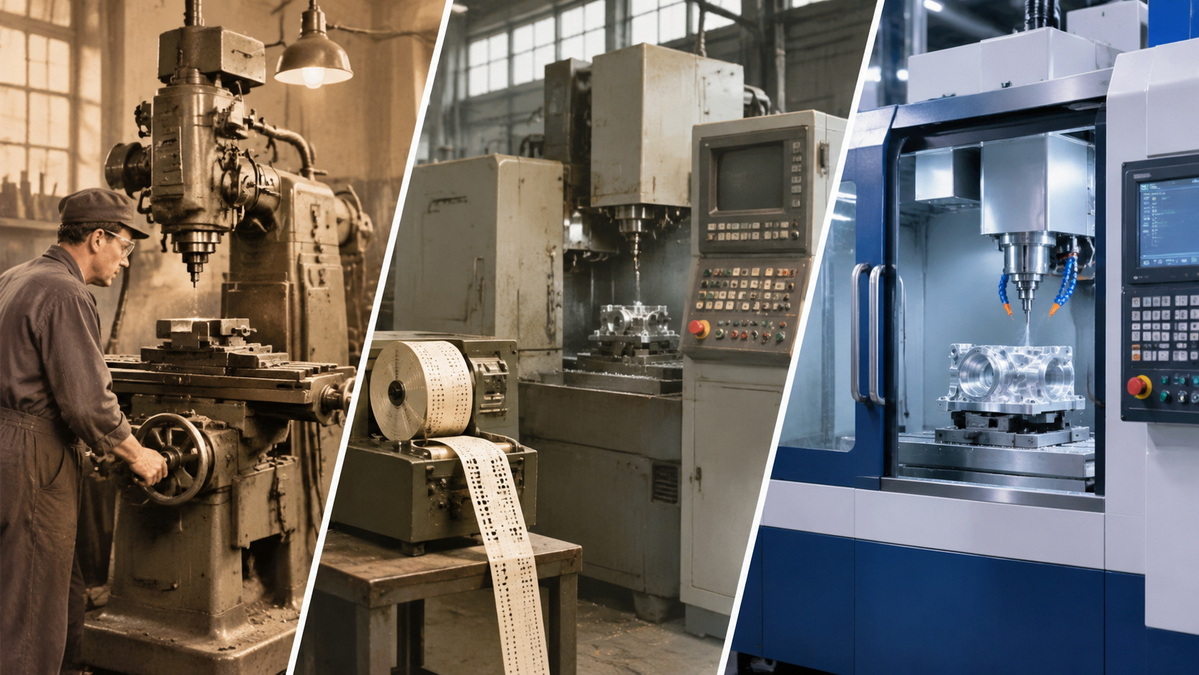
CNC stands for computer numerical control. In CNC machining, a computerized controller executes programmed instructions to coordinate machine movements and operating functions.
Depending on the equipment, these instructions can govern axis positions, feed rates, spindle speeds, and tool changes.
The distinction between NC and CNC is essential to understanding the technology's origins.
Early numerical-control systems followed encoded numerical instructions, commonly supplied on punched paper tape. Later CNC systems incorporated computers into the control architecture, making programs easier to store, edit, and manage.
| Feature | Early NC systems | Modern CNC systems |
|---|---|---|
| Instruction handling | Encoded instructions read through dedicated control hardware | Programs processed by computerized controllers |
| Program changes | Often required preparing or modifying physical media | Usually edited and transferred digitally |
| Programming workflow | Substantial manual preparation | Commonly supported by design and manufacturing software |
| Production integration | More limited connectivity | Can connect with inspection, monitoring, and automation systems |
The change was not simply replacing paper with a screen. It made manufacturing instructions more flexible and easier to reuse.
Before numerical control, machinists relied heavily on drawings, templates, fixtures, measuring instruments, and manual adjustments.
These methods could produce excellent work. However, making complex contours repeatedly demanded considerable skill and preparation.
Aircraft manufacturing intensified the challenge. Curved aerodynamic components required coordinated movements that were difficult to reproduce efficiently through manual operation alone.
The emerging question was straightforward: could calculated coordinates guide machine motion instead of requiring an operator to recreate every movement?
John T. Parsons and Frank L. Stulen are widely associated with the beginnings of numerical control.
Their work connected aircraft-related manufacturing problems with numerical calculations and coordinate-based production methods. Punched-card computing helped turn complex geometry into usable manufacturing information.
Their contributions also reveal an important distinction: calculating a shape and automatically machining that shape are separate engineering problems.
A practical system still needed a way to read instructions, coordinate motion, and control the machine accurately.
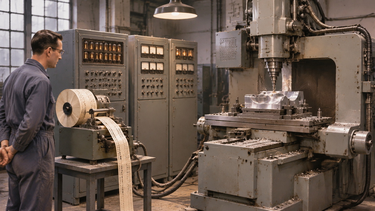
MIT's Servomechanisms Laboratory began its significant numerical-control work in 1949 under a contract with Parsons Corporation.
The laboratory developed an experimental milling machine directed by information on punched paper tape. Its first working continuous-path model was demonstrated in September 1952.
MIT's archival account identifies William M. Pease and James O. McDonough as designers of the experimental machine. Further research continued under U.S. Air Force sponsorship.
The system demonstrated a recognizable control chain:
1. Convert part requirements into numerical instructions.
2. Encode the instructions on punched tape.
3. Read and decode the information.
4. Send control signals to servomechanisms.
5. Drive coordinated machine-axis movements.
Calling this machine a modern CNC system obscures the historical distinction. It was a landmark NC machine that helped establish the foundation for later computerized control.
Its achievement was proving that numerical information could direct complex machining movements.
The evolution of CNC machining involved overlapping advances in control engineering, computing, programming, and machine construction.
| Period | Major development | Practical significance |
|---|---|---|
| 1940s | Parsons and Stulen advance numerical methods for machining problems | Connects calculated geometry with manufacturing instructions |
| 1949 | MIT begins its major numerical-control development project | Brings coordinated motion and control engineering into the project |
| September 1952 | MIT demonstrates a working continuous-path NC milling machine | Demonstrates automated machining from encoded numerical instructions |
| 1950s–1960s | NC systems develop commercially | Expands programmable machine-tool applications |
| 1960s–1970s | Computerized control develops alongside NC | Improves program handling and control flexibility |
| 1970s onward | Microprocessors accelerate controller development | Supports more capable, compact control systems |
| Later decades | Digital programming, multi-axis machining, and connectivity expand | Enables increasingly integrated manufacturing workflows |
| Today | Monitoring, automation, and digital twins extend digital manufacturing | Adds opportunities for prediction, verification, and process improvement |
These stages should not be read as universal adoption dates. Different industries and factories adopted technologies at different speeds.
As computing became practical for machine control, manufacturers gained more flexible ways to manage machining instructions.
One documented example is Siemens' introduction of its Sinumerik 500C computerized control in 1973, initially for turning and milling applications.
Less expensive microprocessors subsequently accelerated development. Networked program management and transfer also became increasingly practical.
This evolution mattered commercially because changing a part no longer depended as heavily on rebuilding physical control media.
Computer-aided design defines part geometry. Computer-aided manufacturing helps programmers develop the machining strategies and toolpaths needed to produce it.
The software does not eliminate manufacturing judgment.
A programmer must still consider:
- Cutting-tool access and rigidity.
- Workholding and setup sequence.
- Material behavior.
- Stock remaining between operations.
- Cutting conditions and chip evacuation.
- Inspection access for critical features.
A digital model describes the intended shape. The manufacturing plan determines how reliably that shape can be produced.
Additional machine axes can help tools reach angled surfaces and complex features with fewer separate setups.
However, more axes do not automatically make a process better or cheaper.
A straightforward component may suit three-axis milling, while a rotational part may be better produced by turning. Complex geometry may justify five-axis machining.
The useful question is not which machine sounds most advanced, but which process meets the part's requirements with manageable cost and risk.
The central lesson is that automation and accuracy are related, but they are not interchangeable.
A machine can repeat a programmed movement while consistently producing an incorrect feature.
From a manufacturing-review perspective, I would evaluate three connected areas.
A supplier needs more than a visual model when functional requirements are important.
Provide clear information about:
- Material grade and condition.
- Critical dimensions and tolerances.
- Datum references.
- Surface finish.
- Threads and fits.
- Heat treatment or coating requirements.
Where a model and drawing differ, establish which document governs before production begins.
Machine capability is only one influence on the finished component.
Tool wear, part deflection, clamping distortion, temperature, and setup changes can also affect results.
For example, a thin wall may move during cutting even when the machine's positioning performance is excellent.
The appropriate response may involve changing the fixture, machining sequence, or geometry—not simply choosing a tighter machine specification.
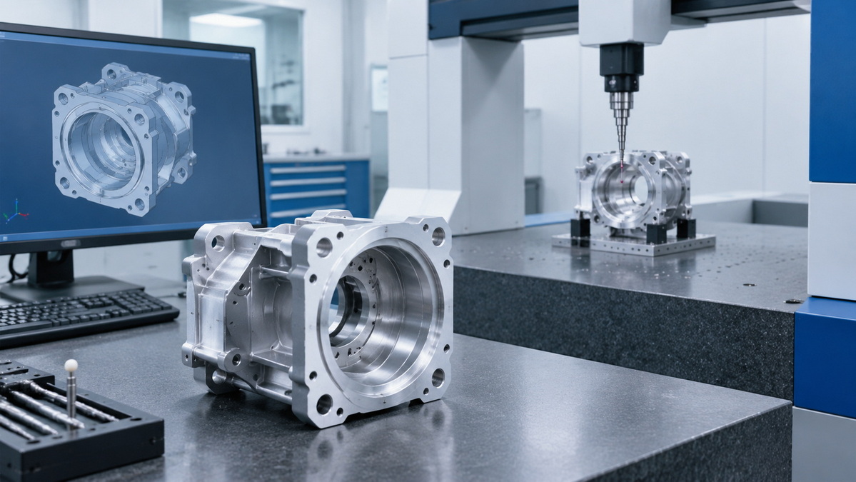
Ask how the supplier will verify important characteristics.
A useful inspection plan identifies the feature, measurement method, acceptance criteria, and reporting requirement.
Depending on geometry, inspection may involve gauges, micrometers, optical measurement, or a coordinate measuring machine.
The instrument should suit the measurement task. A report is valuable only when it verifies the characteristics that determine whether the part works.
Consider an illustrative aluminum housing with a sealing face, bearing bore, mounting holes, and a thin internal wall.
This is a planning example, not a documented U-Need customer project.
A capability-led approach might focus immediately on machine type. A requirement-led approach starts with function.
| Feature | Manufacturing concern | Question to resolve |
|---|---|---|
| Sealing face | Flatness and surface texture | What must the mating interface achieve? |
| Bearing bore | Size, form, and alignment | Which fit and positional relationship are required? |
| Mounting holes | Relationship to assembly datums | How will the housing locate during assembly? |
| Thin wall | Deflection and distortion | Can geometry or operation sequence reduce movement? |
| Finished surfaces | Changes during treatment | Which requirements apply after finishing? |
This approach connects machining history with present-day procurement: programmable motion creates capability, but engineering decisions turn capability into usable parts.
It also helps buyers compare quotations on equivalent requirements rather than price alone.
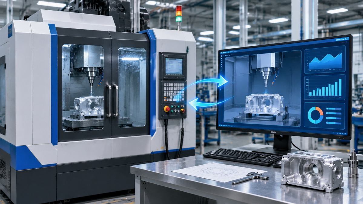
Modern CNC development increasingly extends beyond the controller into connected production systems.
Monitoring can provide information about equipment condition and operating performance. Automation can coordinate handling and machining tasks.
Digital twins add another layer: virtual representations linked with physical manufacturing systems to support analysis, prediction, and optimization.
NIST identifies applications including machine-health analysis, maintenance planning, alternative production schedules, and virtual commissioning.
Its economic research estimates that widespread adoption could create approximately $37.9 billion in annual benefits across U.S. manufacturing.
That figure is a modeled industry-wide opportunity. It is not measured savings from CNC machining alone or a guaranteed return for an individual factory.
NIST also emphasizes validation, interoperability, and uncertainty. A model must represent the real process adequately before its predictions deserve confidence.
For buyers, the practical question remains simple: what measurable improvement does the technology deliver for this project?
Use the following questions to move beyond equipment lists:
1. Can the supplier explain the proposed manufacturing route?
2. Have critical tolerances and datum relationships been reviewed?
3. Are material and finishing requirements clearly included?
4. How will distortion, tool access, and setup changes be managed?
5. Which characteristics will be inspected and reported?
6. How will drawing revisions and production changes be controlled?
7. Does the quotation distinguish prototype and repeat-order requirements?
A strong technical conversation should clarify both capability and limitations.
Answers that identify genuine trade-offs are more useful than blanket promises of exceptional precision.
CNC machining history follows a consistent direction: making manufacturing instructions more controllable, adaptable, and connected.
Yet the fundamentals remain unchanged. Successful parts require clear specifications, suitable processes, stable execution, and meaningful verification.
U-Need supports global brands, distributors, and manufacturers with end-to-end manufacturing solutions in China, including:
- Custom precision parts machining.
- Mold manufacturing, including injection molds, stamping dies, and cold-forging dies.
- Sheet metal fabrication, including laser cutting, bending, and stamping.
The right route may involve machined components, production tooling, fabricated parts, or a combination.
Send U-Need your 3D models, 2D drawings, material requirements, quantities, and target delivery schedule. Identify critical tolerances and finishing requirements so the discussion can focus on manufacturability, process selection, and a clearly scoped quotation.
No single person invented every element of modern CNC machining. Parsons and Stulen helped establish numerical control, MIT developed a landmark working system, and later engineers added computerized controllers and programming capabilities.
MIT demonstrated its first working continuous-path numerically controlled milling machine in September 1952. It followed instructions encoded on punched paper tape rather than using a modern onboard computerized controller.
NC refers broadly to machine control through numerical instructions. CNC incorporates computerized control, enabling more flexible program storage, editing, execution, and integration with digital manufacturing workflows.
Aircraft-related components created demanding contouring and repeatability problems. These requirements encouraged the development of coordinate-based methods and automatic control for movements that were difficult to reproduce efficiently by hand.
No. Results also depend on specifications, machine condition, tooling, fixtures, material behavior, programming, and inspection. Repeatable motion alone does not prove that a finished component meets its functional requirements.
CNC machining can produce mold components, cavities, cores, and related tooling features. Depending on geometry and material condition, a complete tooling process may also require other operations, such as electrical discharge machining, grinding, or polishing.
1. [TOPS — "CNC Machining History: The Origination and Evolution"]. Original article reviewed for topic coverage, historical framing, and content gaps. It was not used as the sole authority for disputed historical claims. [topsbest-precision]
2. [MIT Department of Distinctive Collections — "Massachusetts Institute of Technology, Servomechanisms Laboratory Records"]. Primary archival description supporting the 1949 project, named MIT contributors, punched-tape instructions, and September 1952 demonstration. [archivesspace.mit]
3. [MIT Museum — "A Numerically Controlled Milling Machine"]. Historical film record explaining the 1952 system's punched-tape decoding, servomechanisms, and machine-axis control. [mitmuseum.mit]
4. [Wikipedia — "History of Numerical Control"]. Supplementary historical overview used for the Parsons–Stulen background and the distinction between early numerical control and later computerized systems; MIT records support the central demonstration chronology. [en.wikipedia]
5. [SA Instrumentation & Control — "50 Years of Sinumerik"]. Siemens historical account supporting the 1973 Sinumerik 500C milestone, subsequent microprocessor development, and networked program management. [instrumentation.co]
6. [NIST — "Digital Twins"]. Supports the discussion of manufacturing applications, including machine health, maintenance, scheduling, and virtual commissioning. [nist]
7. [NIST — "Economics of Digital Twins: Costs, Benefits, and Economic Decision-Making"]. Published October 30, 2024. Source of the modeled $37.9 billion industry-wide opportunity and its investment-analysis context. [nist]
8. [NIST — "Digital Twins for Advanced Manufacturing"]. Supports the limitations concerning validation, uncertainty, interoperability, and trustworthy implementation. [nist]


