Views: 251 Author: U-Need Publish Time: 2026-09-29 Origin: Site
Content Menu
● What Is Tight Tolerance Machining?
>> Common Applications for Tight Tolerance Machining
>> What Tight Tolerances Do Not Control
● Tight Tolerance Machining vs GD&T: Key Differences
● When Should You Specify Tight Tolerances?
>> Bearing Fits and Precision Bores
>> Press-Fit Pins and Locating Features
>> High-Precision Mold Components
● When Should You Use GD&T on a CNC Drawing?
>> Use GD&T for Perpendicularity
● The Importance of Functional Datums
● Why Tightening Every Dimension Increases Cost
>> The Cost of Over-Tolerancing
● A Practical Workflow for CNC Drawings
>> 1. Identify Functional Interfaces
>> 2. Select Functional Datums
>> 3. Control Critical Feature Sizes
>> 4. Add GD&T for Geometric Relationships
>> 5. Specify Surface Finish and Edge Requirements
>> 6. Define the Inspection Method
● Example: CNC-Machined Sensor Housing
● Applying GD&T to Mold Manufacturing
>> Common Mold Features That Need Careful Control
● Applying GD&T to Sheet Metal Fabrication
>> Useful Controls for Sheet Metal Parts
● Common CNC Drawing Mistakes to Avoid
>> Applying Tight Tolerances to Non-Critical Dimensions
>> Using Hole Coordinates Without Position Control
>> Choosing Non-Functional Datums
>> Omitting Surface Finish Requirements
>> Leaving Burr Requirements Unclear
>> Failing to State the Drawing Standard
● What Should Be Included on a CNC Drawing?
● Summary: Tight Tolerance Machining vs GD&T
>> 1. Is GD&T better than tight tolerances?
>> 2. Does every CNC machined part need GD&T?
>> 3. What is the most useful GD&T control for CNC machining?
>> 4. Does a tight hole diameter tolerance control hole location?
>> 5. Can GD&T reduce CNC machining cost?
>> 6. Should I use ASME or ISO GD&T standards?
>> 7. What files should be provided for a CNC machining quotation?
A CNC drawing should do more than list dimensions. It should explain how a part must fit, locate, seal, rotate, assemble, and perform in the finished product. This is why engineers often need to decide between tight tolerance machining and GD&T when preparing manufacturing drawings.
The answer is not to choose one over the other. Tight tolerances control feature size. GD&T controls feature geometry and functional relationships. A well-prepared drawing uses each method where it creates real value.
For example, a bearing bore may require a tightly controlled diameter to achieve the correct fit. At the same time, the bore axis may need to remain perpendicular to a mounting face and accurately located relative to surrounding holes. A size tolerance alone cannot define those geometric requirements.
For global brands, distributors, product developers, and manufacturers, clear tolerancing is essential for controlling quality, quotation accuracy, production consistency, inspection methods, and total manufacturing cost. It also helps reduce delays caused by drawing interpretation differences between engineering teams, suppliers, and quality inspectors.
At U-Need, we support custom precision parts machining, mold manufacturing, and sheet metal fabrication projects for customers who need reliable communication from drawing review through production and inspection. The most effective drawings are not simply those with the tightest requirements. They are the drawings that communicate the true functional intent of the part.
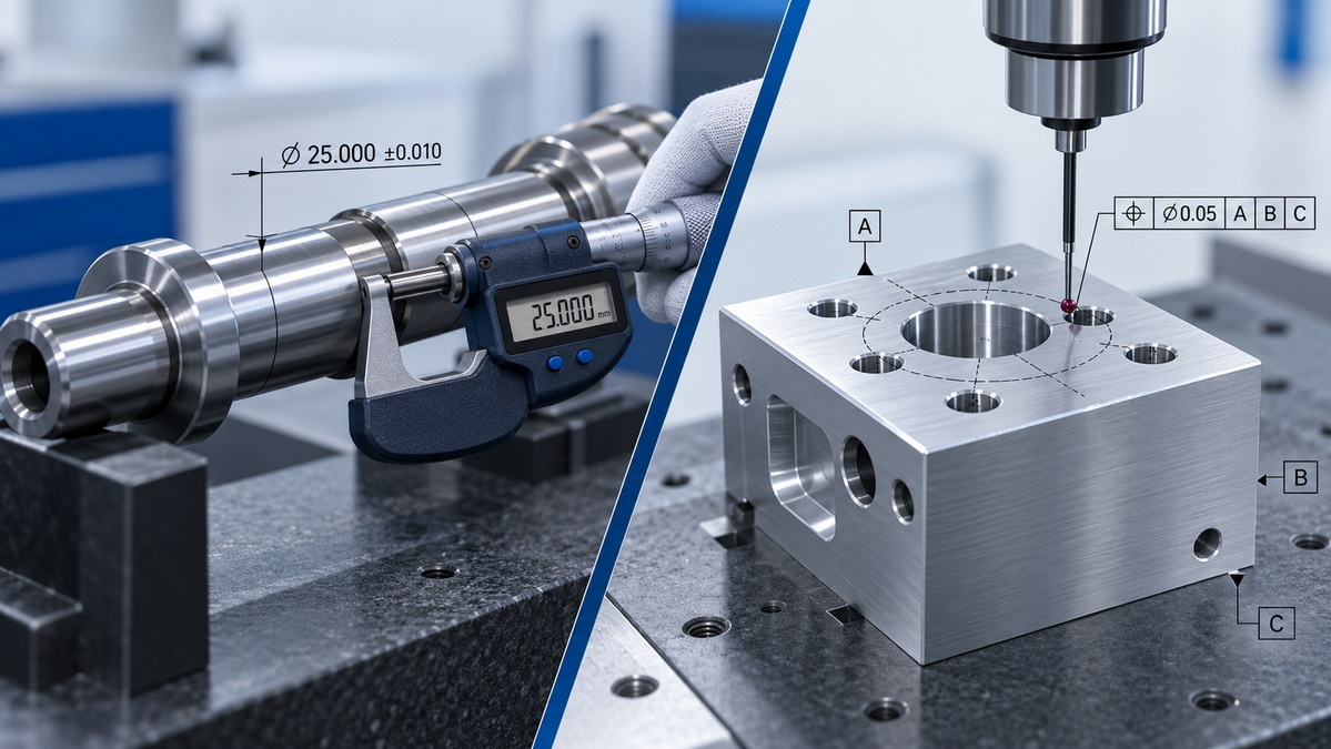
Tight tolerance machining means producing a feature within a narrow allowable dimensional range. It is commonly used when small variations in size could affect fit, sealing, movement, load transfer, alignment, or product performance.
A conventional tolerance is usually shown as a plus/minus value, a limit dimension, or a standard fit callout.
The specified range is only 0.010 mm wide. Manufacturing a feature within this range may require stable CNC equipment, precision workholding, controlled cutting parameters, accurate inspection tools, and careful process planning.
Tight dimensional tolerances are often necessary for the following features:
- Bearing bores and bearing seats
- Precision shafts and journals
- Press-fit pins and dowel holes
- Bushing bores
- Gear seats and coupling diameters
- Hydraulic and pneumatic sealing diameters
- O-ring gland dimensions
- Mold inserts and mold cavity components
- Precision fixture locations
- Medical-device components
- Automation equipment parts
- High-accuracy tooling components
For these applications, the actual size of the feature directly affects whether the part will assemble and function correctly.
A tight size tolerance does not automatically control every aspect of a feature.
However, the hole may still be:
- Too far from its intended location
- Tilted relative to the main mounting surface
- Misaligned with a mating hole
- Offset from a centerline
- Out of alignment with another bore
- Functionally unsuitable for a screw, pin, shaft, or connector
This is the limitation of relying only on standard dimensional tolerances. The size may be correct, but the feature may not work correctly in the final assembly.
GD&T, short for Geometric Dimensioning and Tolerancing, is an engineering language used to define the allowable variation in a part's geometry.
Instead of only controlling the size of a feature, GD&T can define whether a surface is flat, whether a hole is properly located, whether a bore is perpendicular to a face, whether a shaft rotates smoothly, or whether a complex profile stays within an acceptable zone.
GD&T is particularly valuable for precision CNC machined parts, injection mold components, stamping dies, sheet metal parts, assemblies, and components with multiple functional interfaces.
GD&T controls are generally divided into several categories.
| GD&T Category | Typical Controls | What It Helps Control |
|---|---|---|
| Form | Straightness, flatness, circularity, cylindricity | The shape of a feature itself |
| Orientation | Parallelism, perpendicularity, angularity | The angle of a feature relative to a datum |
| Location | Position, concentricity, symmetry | The location of a feature relative to other features |
| Profile | Profile of a line, profile of a surface | Complex contours, surfaces, and shapes |
| Runout | Circular runout, total runout | Rotational accuracy of cylindrical or rotating parts |
In practice, GD&T gives engineers and manufacturers a clearer way to communicate functional requirements.
A CNC drawing with properly selected GD&T can reduce ambiguity, improve repeatability, and make it easier to establish a consistent inspection method.
Tight tolerance machining and GD&T are often discussed together, but they serve different purposes.
| Comparison Factor | Tight Tolerance Machining | GD&T |
|---|---|---|
| Main purpose | Controls feature size | Controls geometry and relationships between features |
| Typical format | ± tolerance, limits, fit class | Feature control frame, datum references, basic dimensions |
| Example | Ø20.00 ±0.02 mm | Position Ø0.05 relative to A-B-C |
| Best for | Diameter, thickness, width, depth, fit | Location, flatness, orientation, profile, runout |
| Controls hole location | No, not directly | Yes |
| Controls angle or tilt | No | Yes |
| Controls surface flatness | No | Yes |
| Controls rotational accuracy | No | Yes |
| Inspection tools | Micrometer, caliper, bore gauge | CMM, height gauge, functional gauge, dial indicator |
| Cost impact | Can increase cost if overused | Can improve clarity and reduce unnecessary tolerance demands |
The most important difference is this:
> A dimensional tolerance answers "How big can this feature be?" GD&T answers "How must this feature behave relative to the part and assembly?"
Specify a tight tolerance when the actual size of a feature directly affects product function.
This is especially important when a component must create a controlled clearance, interference, press fit, seal, sliding condition, or bearing relationship.
A bearing bore usually requires accurate diameter control because the fit between the bearing outer ring and housing directly affects performance.
If the bore is too small, installation may require excessive force and may damage the bearing. If it is too large, the bearing can move, spin, or lose alignment during use.
However, this size requirement alone may not be enough. The bore may also need to be perpendicular to a mounting face, aligned with another bore, and controlled for surface finish.
Dowel pins, press-fit inserts, and locating pins depend on controlled diameters.
If the hole is oversized, the pin may be loose. If the hole is undersized, assembly may become difficult or may deform the component.
Tight tolerance machining is often necessary for:
- Alignment dowel holes
- Press-fit bushings
- Metal inserts in aluminum parts
- Mold guide pin holes
- Precision assembly fixtures
- Automated equipment locating pins
Sealing features often require controlled diameters, depths, and surface conditions.
Common examples include:
- O-ring grooves
- Hydraulic cylinder diameters
- Pump housings
- Valve seats
- Mechanical seal interfaces
- Fluid connector ports
A small variation in size can cause leakage, excessive friction, poor compression, or premature seal failure.
Injection molds, stamping dies, and cold-forging dies often include tightly toleranced inserts, guide components, cavity features, and alignment elements.
Precision is important because tooling components must repeatedly open, close, align, guide material, and maintain stable part geometry across long production runs.
Use GD&T when a feature must maintain a defined geometric relationship with other features.
The need for GD&T becomes stronger as part complexity increases. It is especially useful for parts with hole patterns, sealing faces, rotating features, precision assemblies, multiple machining setups, or critical mating components.
Position tolerance is one of the most useful controls for CNC machining.
It is commonly applied to:
- Bolt-hole patterns
- Dowel holes
- Connector mounting holes
- Threaded hole arrays
- Multi-axis machined features
- Mounting holes in housings
- Mold component locating holes
- Sheet metal fastening holes
A hole can have the correct diameter but still fail if it is misplaced. Position tolerance controls the acceptable movement of the hole axis relative to designated datum features.
This is especially valuable when several holes must align with a mating component.
Flatness controls how much a surface may vary from a perfectly flat condition.
It is especially useful for:
- Gasket surfaces
- O-ring sealing faces
- Valve mounting faces
- Heat sink mounting surfaces
- Mold base surfaces
- Fixture plates
- Precision assembly surfaces
- Sheet metal panels that must sit flush
For example, a machined sealing face may require:
> Flatness 0.05 mm
This means the entire surface must remain within two imaginary parallel planes separated by 0.05 mm.
A surface may have a correct overall thickness but still be warped, uneven, or unsuitable for sealing. Flatness addresses that functional risk.
Perpendicularity controls whether a feature is properly oriented at 90 degrees relative to a datum surface, datum axis, or datum plane.
It is often applied to:
- Bore axes relative to mounting faces
- Threaded holes on sealing surfaces
- Sidewalls relative to a base
- Press-fit holes
- Guide pin holes
- Fixture alignment features
- Vertical bores in machined housings
A hole can have the right diameter and correct surface location but still tilt enough to prevent smooth assembly. Perpendicularity prevents this condition.
Parallelism controls whether one feature remains parallel to another datum feature.
It is useful for:
- Sliding surfaces
- Guide rails
- Fixture plates
- Spacer faces
- Parallel machined blocks
- Mold plates
- Linear motion components
- Opposing contact surfaces
For two parallel faces, it may be more meaningful to control parallelism than to apply an extremely tight thickness tolerance to both surfaces.
Profile tolerance is one of the most flexible tools in GD&T.
It can control a complex shape, surface contour, orientation, and location. It is especially valuable for features that cannot be defined efficiently using many individual linear dimensions.
Typical uses include:
- Curved CNC-machined surfaces
- Mold cavities and cores
- Complex aluminum housings
- Aerospace-style components
- Ergonomic product contours
- Sheet metal formed shapes
- Forged or cast surfaces
- Complex transition areas between machined features
Instead of adding many separate tolerances to every point on a complex surface, a profile tolerance can define the allowed variation over the full contour.
Runout controls how much a rotating feature can vary when the part rotates around a datum axis.
This is critical for components such as:
- Motor shafts
- Spindles
- Rotors
- Gear seats
- Bearing journals
- Pulleys
- Rollers
- Rotating hubs
- Precision cylindrical assemblies
A shaft may have the correct diameter but still wobble during rotation. Excessive runout can lead to vibration, noise, bearing wear, uneven loading, reduced accuracy, and premature product failure.
A datum is a reference feature used to establish how a part is located for manufacturing and inspection.
Datums are the foundation of useful GD&T. If the datum scheme does not reflect the real assembly condition, even a technically correct drawing may not produce functionally consistent parts.
A good datum selection process begins with the real-world assembly.
Ask the following questions:
- Which surface contacts the main assembly?
- Which feature locates the part left to right?
- Which hole, edge, or face prevents rotation?
- Which feature establishes the functional centerline?
- Which surface carries the sealing load?
- Which geometry is most important to the customer's assembly?
A common datum structure may include:
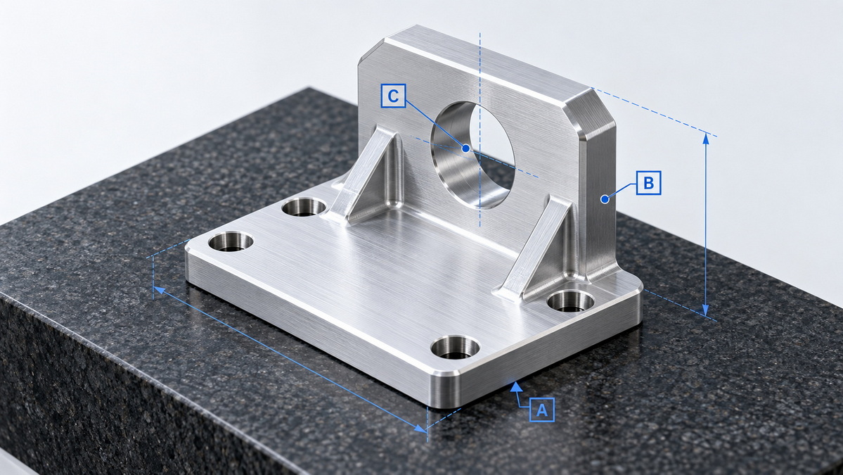
- Datum A: The main mounting, seating, or sealing surface
- Datum B: A secondary side face, bore, or center plane
- Datum C: A third feature that prevents remaining movement or rotation
For example, a CNC-machined mounting bracket may use its bottom face as datum A, its side face as datum B, and one locating hole as datum C.
This setup reflects how the part may sit in the actual assembly fixture.
Without a functional datum system, multiple suppliers may inspect the same drawing differently.
One supplier may measure from an outer edge. Another may use a hole center. A third supplier may use a fixture that does not represent the actual assembly position.
The result can be parts that appear acceptable during inspection but do not assemble consistently.
A common but costly approach is to apply tight ± tolerances to nearly every dimension on a drawing.
This may seem like a safe method for ensuring quality, but it can create unnecessary manufacturing complexity.
When almost every dimension has a narrow tolerance, manufacturers may need to use:
- Additional CNC setups
- Precision fixtures and soft jaws
- More stable cutting strategies
- Extra tool probing
- Slower machining cycles
- More frequent in-process measurement
- CMM inspection
- Dedicated gauges
- Tighter raw material control
- Higher scrap allowances
- More experienced operators
- Additional quality documentation
Each of these factors can increase unit cost and production lead time.
The problem is not tight tolerances themselves. The problem is applying them where they do not create functional value.
Instead of asking:
> "How tight can this tolerance be?"
Ask:
> "How much variation can this feature allow while the assembly still works reliably?"
This is the foundation of a practical tolerance strategy.
A non-critical exterior dimension may only need a general tolerance. A hidden pocket may not require tight positional control. A cosmetic edge may not need the same accuracy as a bearing bore or sealing face.
By concentrating precision on functional features, engineers can reduce cost without sacrificing performance.
A clear CNC drawing should be developed in a structured sequence.
Start by identifying the areas where the part connects, seals, rotates, supports load, or interfaces with another component.
Review:
- Mounting faces
- Bolt-hole patterns
- Bearing seats
- Locating pins
- Sealing surfaces
- Threads
- Sliding surfaces
- Gear and coupling interfaces
- Electrical connector features
- Cosmetic surfaces
- Critical internal pockets
Not every dimension has equal importance. Focus on the features that determine whether the final product works.
Choose datum features based on how the part is located during assembly.
A useful question is:
> "If this part were placed into the final product, which features would touch first, locate next, and stop movement last?"
The answer often reveals the correct datum sequence.
Apply dimensional tolerances to features where exact size controls fit or performance.
Examples include:
- Shaft diameters
- Bearing bores
- Press-fit holes
- Sealing diameters
- Thread sizes
- Wall thicknesses
- Keyways
- Bushing seats
- Tooling inserts
Use the narrowest tolerance that is truly required for the function.
Apply GD&T only where geometry matters.
Common examples include:
- Position for a hole pattern
- Flatness for a gasket face
- Perpendicularity for a bore axis
- Parallelism for a sliding surface
- Profile for a complex contour
- Runout for a rotating diameter
The goal is to define critical functional relationships without over-controlling every feature.
Dimensions and GD&T are not the complete story.
A drawing may also need to define:
- Surface roughness
- Deburring requirements
- Edge breaks
- Chamfers
- Fillets
- Sharp-edge limits
- Coating thickness
- Anodizing requirements
- Plating requirements
- Painting or powder coating
- Masking areas
- Heat treatment
- Hardness
- Material certification needs
For example, a precision bore with a rough surface may damage a seal or prevent a bearing from seating properly. A burr on a threaded hole may interfere with assembly. A coating may change the final dimension of a critical feature.
Before releasing a drawing, consider how the critical requirements will be verified.
| Feature Requirement | Common Inspection Method |
|---|---|
| External shaft diameter | Micrometer |
| Internal bore diameter | Bore gauge, air gauge, CMM |
| Hole position | CMM, height gauge, inspection fixture |
| Surface flatness | CMM, surface plate, indicator |
| Perpendicularity | CMM, height gauge, indicator setup |
| Parallelism | Surface plate, indicator, CMM |
| Circular or total runout | Dial indicator and rotation fixture |
| Surface profile | CMM, optical scanner, inspection fixture |
| Surface roughness | Surface roughness tester |
A requirement should be clear enough that the manufacturer and inspector can verify it using a repeatable method.
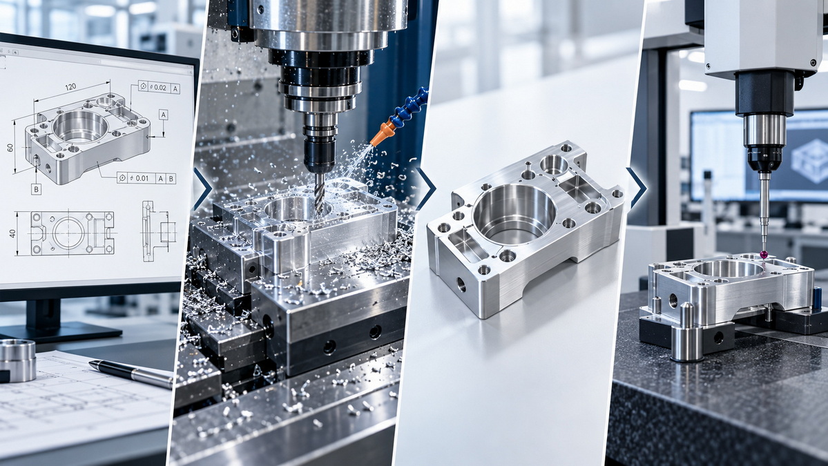
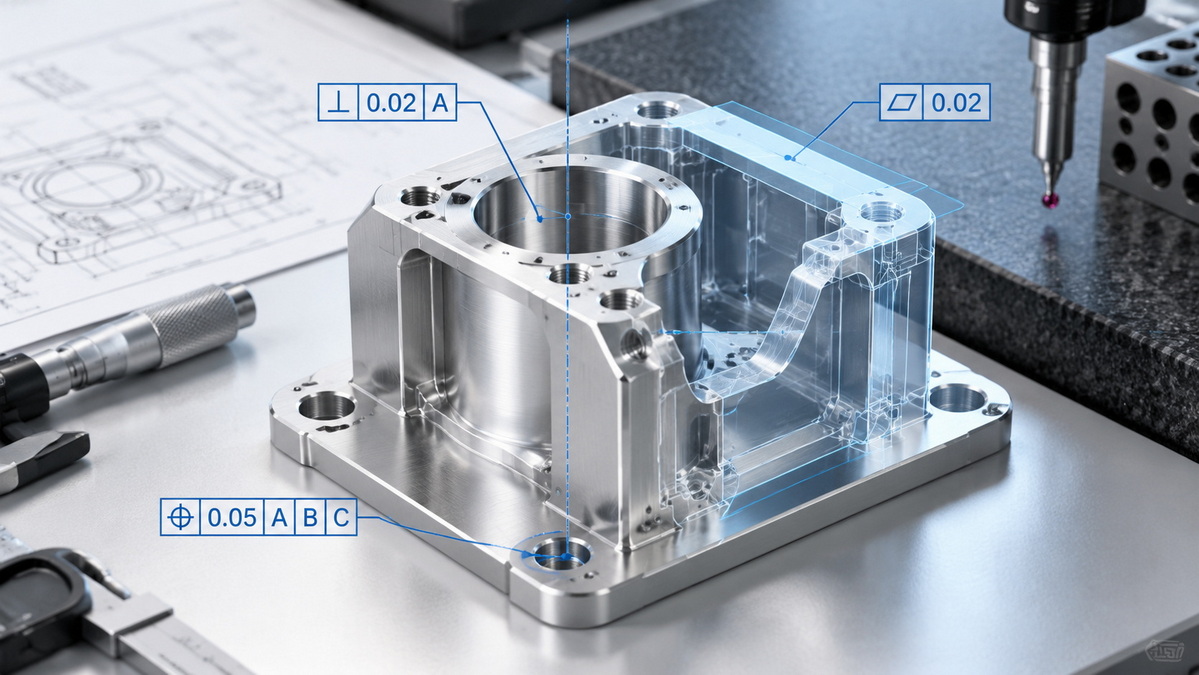
Consider an aluminum sensor housing with the following features:
- A bottom mounting face
- Four mounting holes
- A central precision bore
- A sealing face for a cover
- An internal electronics pocket
- Exterior cosmetic surfaces
A poorly specified drawing might apply ±0.02 mm tolerances to nearly every linear dimension.
This can make machining more expensive, but it may still fail to control the features that matter most.
For example, the central bore could have the correct diameter but be tilted relative to the mounting face. The bolt holes could be correctly sized but not align with the mating cover. The sealing surface could meet its thickness requirement but still lack sufficient flatness.
A more functional drawing could specify:
- Datum A: Bottom mounting face
- Datum B: Machined side face
- Datum C: One locating hole
- Central bore: Controlled diameter with perpendicularity relative to datum A
- Mounting holes: Position tolerance relative to A-B-C
- Sealing face: Flatness requirement
- Internal pocket contour: Profile tolerance relative to A-B-C
- External cosmetic dimensions: General tolerance where function allows
This approach places manufacturing effort where it matters most.
> The goal is not to make every feature perfect. The goal is to make every function reliable.
Mold manufacturing often requires a combination of precise sizes and carefully controlled geometric relationships.
Injection molds, stamping dies, and cold-forging dies depend on accurate alignment between multiple plates, inserts, guide components, cavities, cores, and moving mechanisms.
Typical examples include:
- Guide pin holes
- Guide bushing bores
- Mold insert locations
- Cavity and core alignment
- Ejector pin holes
- Slider guide surfaces
- Parting surfaces
- Cooling channel locations
- Mold plate flatness
- Parallelism between mold plates
- Profile accuracy of cavity surfaces
A guide pin hole may require a tight diameter tolerance. However, it may also need positional accuracy relative to the mold base and perpendicularity relative to the plate surface.
Similarly, a mold cavity may need a profile tolerance because the full surface shape matters more than isolated linear dimensions.
GD&T is also useful in laser cutting, bending, stamping, welding, and sheet metal assembly.
Sheet metal parts can experience variation during material cutting, bending, welding, stress relief, surface finishing, and assembly. Applying extremely tight linear tolerances to every feature may be unrealistic and unnecessarily expensive.
For sheet metal fabrication, consider using:
- Position tolerance for mounting holes
- Profile tolerance for formed contours
- Flatness for mounting panels
- Perpendicularity for bent flanges
- Angularity for formed features
- Datum-based location control for assembly interfaces
- General tolerances for non-critical cut edges
For example, a bent sheet metal bracket may need holes that align with a mating enclosure. The hole pattern can be controlled using position relative to functional datums rather than relying only on coordinate dimensions.
This provides a clearer assembly requirement and helps manufacturers choose practical inspection methods.
Do not use tight tolerances as a general quality statement.
A tight tolerance should have a functional reason. If the feature does not affect fit, sealing, movement, strength, safety, or appearance, a general tolerance may be sufficient.
Coordinate dimensions can create tolerance stack-up.
For multi-hole patterns, position tolerance can better define the true functional location of each hole relative to the datum system.
A datum should reflect how the part is assembled, mounted, or inspected.
Avoid selecting arbitrary edges or surfaces simply because they are convenient in the CAD model.
A feature may meet its dimensional requirement but still fail due to poor surface quality.
Surface finish is especially important for:
- Sealing faces
- Bearing seats
- Sliding surfaces
- Precision bores
- Mold cavities
- Cosmetic surfaces
- Coated contact areas
Anodizing, plating, painting, powder coating, and other finishing processes can change final dimensions.
Critical holes, threads, bearing seats, and precision mating surfaces may require masking or post-finishing machining.
Burrs can interfere with assembly, create safety risks, damage seals, or prevent proper seating.
Add clear deburring and edge-break requirements, especially around holes, threads, machined edges, and sealing features.
When working with international suppliers, clearly state the drawing standard and units.
This helps avoid differences in symbol interpretation, default tolerances, decimal conventions, inspection expectations, and general drafting practices.
A complete CNC drawing should provide enough information for manufacturing and inspection without creating unnecessary complexity.
Include the following where applicable:
- Part number and revision level
- Part name and quantity
- Units of measurement
- Scale and projection method
- Material grade
- Material certification requirements
- Heat treatment and hardness
- Surface treatment or coating requirements
- General tolerance standard
- Functional datums
- Critical dimensional tolerances
- GD&T feature control frames
- Surface roughness requirements
- Thread specifications
- Chamfer and radius requirements
- Deburring instructions
- Edge-break requirements
- Critical-to-function feature identification
- Inspection documentation requirements
- Packaging and corrosion-protection requirements
- Assembly notes when relevant
For complex or high-value components, it is often useful to supply both a detailed 2D drawing and a 3D CAD model.
The 2D drawing defines the production and inspection requirements. The 3D model helps clarify shape, reduce interpretation time, and support CNC programming.
Tight tolerance machining and GD&T should be used together, not treated as alternatives.
Tight tolerances define how large, small, thick, thin, wide, or deep a feature may be.
GD&T defines how a feature must relate to other features in terms of location, orientation, form, profile, and runout.
A high-quality CNC drawing should:
- Use tight tolerances only for function-critical sizes
- Use functional datums that reflect the real assembly condition
- Apply GD&T to control important geometric relationships
- Avoid unnecessary tolerances on non-critical features
- Define surface finish, edges, materials, coatings, and inspection needs
- Make it possible for the manufacturer and quality team to inspect the part consistently
For custom precision parts machining, mold manufacturing, and sheet metal fabrication, drawing clarity is one of the strongest factors affecting cost, lead time, quality, and repeatability.
U-Need helps customers evaluate drawings, identify manufacturability concerns, clarify tolerance strategy, and prepare precision components for reliable production. Sharing a 2D drawing together with a 3D model allows the manufacturing team to review critical features, machining feasibility, inspection methods, and production requirements before manufacturing begins.
GD&T is not better in every situation because it solves a different problem. Tight tolerances control the size of a feature, while GD&T controls geometry and relationships between features. Precision parts often require both.
No. Simple parts with low functional risk may only require conventional dimensions and general tolerances. GD&T becomes more useful when a part includes hole patterns, bearing bores, sealing surfaces, rotating features, critical assemblies, or complex shapes.
Position tolerance is one of the most commonly used controls because it accurately defines the location of holes, slots, pins, and feature patterns relative to functional datums.
No. A tight diameter tolerance only controls the size of the hole. It does not control whether the hole is in the correct position, whether its axis is perpendicular, or whether it aligns with mating features.
Yes. Proper GD&T can reduce cost by communicating the true functional requirement rather than requiring extremely tight linear tolerances on every feature. It can also reduce inspection ambiguity and help avoid unnecessary rework.
The appropriate standard depends on your customer requirements, target market, internal engineering practices, and project documentation. Clearly identify the governing standard on the drawing so that all parties use the same interpretation.
For an accurate quotation, provide a 2D PDF drawing and a 3D CAD model. The drawing should include material, quantity, tolerances, GD&T, surface finish, coating, and any inspection or certification requirements. Common 3D formats include STEP, IGES, Parasolid, and native CAD files where available.
1. American Society of Mechanical Engineers. *Y14.5: Dimensioning and Tolerancing.*
[https://www.asme.org/codes-standards/find-codes-standards/y14-5-dimensioning-tolerancing]
2. National Institute of Standards and Technology. *Investigating the Role of Geometric Dimensioning and Tolerancing in Manufacturing.*
[https://tsapps.nist.gov/publication/get_pdf.cfm?pub_id=918538]
3. National Institute of Standards and Technology. *Geometric Dimensioning and Tolerancing for Digital Manufacturing.*
[https://tsapps.nist.gov/publication/get_pdf.cfm?pub_id=936463]
4. International Organization for Standardization. *ISO 1101: Geometrical Product Specifications (GPS) — Geometrical Tolerancing.*
[https://www.iso.org/standard/59490.html]
5. Standards New Zealand. *ISO 1101:2017 — Geometrical Tolerancing.*


