Views: 259 Author: U-Need Publish Time: 2026-09-27 Origin: Site
Content Menu
● What Is Tight Tolerance Machining?
>> Why Tight Tolerances Matter
● What Are Surface Finish Requirements?
● Why Surface Finish Matters in Precision Manufacturing
● Tight Tolerance Machining vs Surface Finish Requirements
● When Should Engineers Prioritize Tight Tolerances?
>> Bearing Seats and Bearing Housings
>> Locating Holes and Dowel Pin Features
>> Mold Inserts and Tooling Components
● When Should Engineers Prioritize Surface Finish Requirements?
>> Sliding and Rotating Components
>> Fatigue-Critical Components
>> Cosmetic and Consumer-Facing Components
● When Both Requirements Are Critical
● The Cost of Over-Specification
● A Practical Method for Setting Requirements
>> 1. Identify the Feature's Function
>> 2. Identify the Failure Mode
>> 3. Use Clear Datum References
>> 4. Apply Surface Finish Only Where It Matters
>> 5. Consider the Full Manufacturing Sequence
● Why Smoother Is Not Always Better
>> Precision Mold Manufacturing
>> Hydraulic and Pneumatic Components
>> Custom Precision Machined Parts
● Better Drawing and RFQ Requirements
● FAQ
>> 1. What is considered a tight tolerance in CNC machining?
>> 2. Is Ra the only surface finish value that matters?
>> 3. Does a finer surface finish always increase machining cost?
>> 4. Can polishing change the final dimensions of a part?
>> 5. Should a sealing surface have both flatness and roughness requirements?
>> 6. What surface finish is common for CNC machined parts?
>> 7. How can engineers avoid over-specifying machining tolerances?
When engineers compare tight tolerance machining and surface finish requirements, the correct priority is rarely one or the other. The more useful question is: Which requirement has the greatest impact on the part's real-world function?
A component can be dimensionally accurate but still fail because it leaks, wears too quickly, sticks during movement, develops fatigue damage, or performs poorly after coating. In the same way, a highly polished part may still be unusable if its bore diameter, flatness, concentricity, or hole position is outside the acceptable range.
For global manufacturers, distributors, and product-development teams, the most practical approach is to define requirements according to the function of each feature. Tight tolerances should protect fit, assembly, alignment, and motion. Surface finish requirements should protect friction, sealing, wear resistance, fatigue performance, corrosion resistance, coating quality, and appearance.
The goal is not to specify the tightest tolerance and the lowest possible roughness value on every surface. The goal is to create a part that performs reliably, can be inspected consistently, and can be manufactured efficiently.
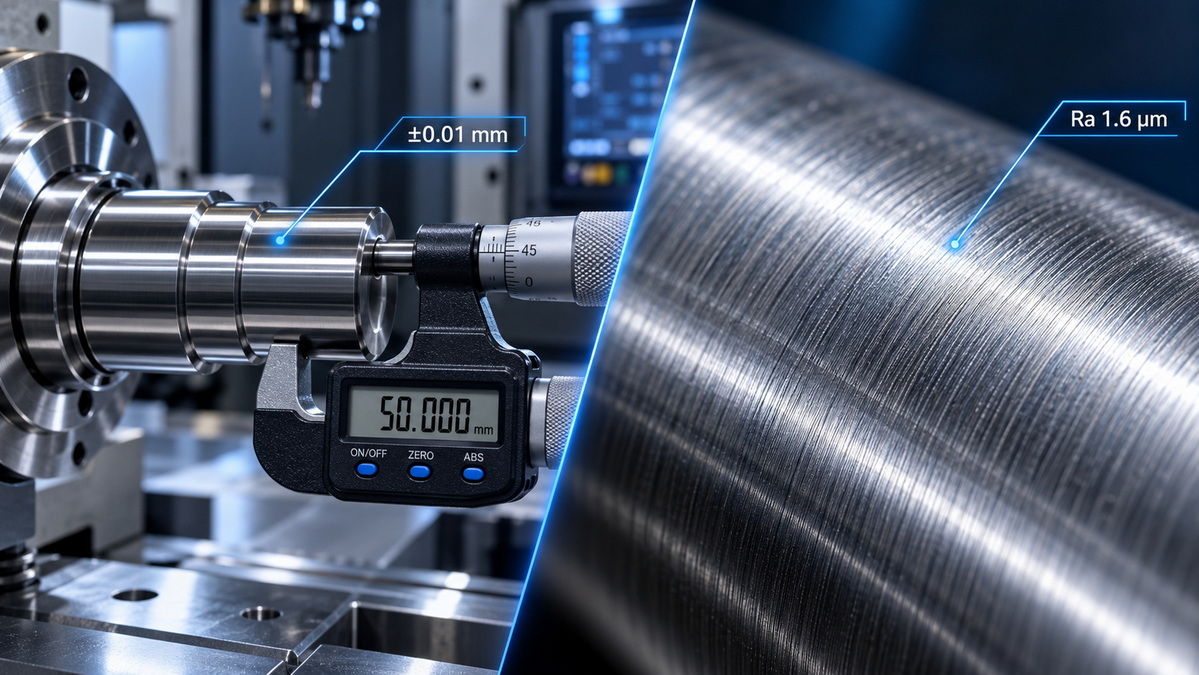
Tight tolerance machining is the process of manufacturing a component within a narrow allowable variation from its nominal dimensions. A tolerance defines how much a dimension, form, orientation, or location may vary while still being acceptable.
For example, a shaft diameter specified as 10.00 mm ±0.01 mm must measure between 9.99 mm and 10.01 mm. Any part outside that range may be rejected, reworked, or cause assembly problems.
Tight tolerances can apply to basic dimensions, but they also apply to geometric requirements that influence how components mate and move together.
Common tight tolerance machining controls include:
- Diameter
- Length
- Width
- Thickness
- Flatness
- Straightness
- Roundness
- Cylindricity
- Concentricity
- Perpendicularity
- Parallelism
- True position
- Runout
- Profile
A precision-machined component may require a bore held within a narrow range for a press-fit bearing. A mold insert may require high positional accuracy to align with a mating core. A stamped component may need precisely located holes to fit an automated assembly fixture.
However, a tight tolerance does not automatically mean a part is better. It only adds value when the requirement supports a specific functional need.
Tight tolerances are usually necessary when incorrect geometry would prevent assembly, reduce accuracy, create vibration, or shorten the service life of the product.
They are especially important for:
- Bearing seats and bearing housings
- Press-fit or interference-fit features
- Precision shafts and bores
- Locating pin holes
- Gearbox components
- Valve bodies and fluid-control parts
- Mold inserts and core components
- Medical device components
- Aerospace assemblies
- Robotics and automation equipment
- Precision fixture components
For example, a bearing bore may need a tightly controlled diameter, roundness, and cylindricity. If the bore is too large, the bearing may rotate within the housing. If it is too small, excessive interference may create unwanted preload, distortion, heat generation, or difficult assembly.
In this case, the primary concern is geometry. A fine surface finish may help the assembly process, but it cannot correct an incorrect bearing-seat diameter.
Surface finish requirements define the texture and condition of a component's surface after machining, grinding, polishing, stamping, forming, coating, or other manufacturing processes.
A surface is not perfectly smooth. Even a high-quality machined part contains microscopic peaks, valleys, tool marks, and directional patterns. These characteristics can influence how the part seals, slides, wears, reflects light, retains lubricant, accepts coating, resists corrosion, or interacts with another component.
Surface finish normally includes three related characteristics:
- Roughness: Fine and closely spaced surface irregularities
- Waviness: Larger and more widely spaced surface variations
- Lay: The main direction of the surface pattern produced by the manufacturing process
The most common surface texture value on engineering drawings is Ra, also called arithmetic average roughness. Ra is usually expressed in micrometers, such as Ra 3.2 µm, Ra 1.6 µm, or Ra 0.8 µm.
A lower Ra value generally indicates a smoother surface. However, Ra alone does not fully describe surface performance.
Two surfaces can have the same Ra value but behave very differently because of differences in peak shape, valley depth, waviness, machining direction, or material ratio.
For demanding applications, engineers may also evaluate:
- Rz
- Rq
- Material ratio
- Waviness
- Peak height
- Valley depth
- Bearing-area characteristics
- Lay direction
- Surface defects
- Scratches and chatter marks
Surface finish requirements are often associated with appearance, but their role is much broader. In many applications, surface texture is a critical functional requirement.
A poor surface finish can lead to:
- Fluid leakage
- Gas leakage
- High friction
- Galling
- Accelerated wear
- Reduced fatigue life
- Poor lubrication performance
- Unstable coating adhesion
- Corrosion initiation
- Difficult cleaning
- Poor cosmetic quality
- Poor mold release
- Visible machining marks
A sealing face can meet its dimensional tolerance but still leak if it has deep machining grooves, excessive waviness, scratches, burrs, or directional tool marks that create leakage paths.
A sliding shaft can meet its diameter requirement but still wear prematurely if the surface is too rough, too irregular, or unsuitable for lubricant retention.
A polished mold cavity can improve the gloss of an injection-molded product, but a highly polished cavity may not be suitable for a product requiring a textured, matte, leather-grain, or anti-slip surface.
The correct surface finish is not always the smoothest possible surface. It is the surface that supports the intended function.
Tight tolerances and surface finish requirements influence different aspects of part performance. One controls the geometry of the feature. The other controls the quality of the surface itself.
| Comparison Factor | Tight Tolerance Machining | Surface Finish Requirements |
|---|---|---|
| Main purpose | Controls size, position, form, and orientation | Controls surface texture, contact behavior, and surface quality |
| Typical callout | ±0.01 mm, H7 fit, position 0.05 mm, flatness 0.02 mm | Ra 3.2 µm, Ra 1.6 µm, Ra 0.8 µm, Rz limit |
| Primary performance impact | Fit, alignment, assembly, interchangeability, accuracy | Sealing, friction, wear, fatigue, coating, appearance |
| Typical inspection method | CMM, micrometer, bore gauge, pin gauge, optical inspection | Profilometer, roughness tester, optical surface measurement |
| Main manufacturing challenge | Stable workholding, thermal control, machine accuracy, inspection repeatability | Tool condition, feed rate, cutting parameters, grinding, polishing, inspection |
| Main cost driver | Extra setups, slower machining, special fixtures, tighter inspection | Fine finishing passes, grinding, honing, polishing, additional testing |
| Typical risk if ignored | Loose fit, interference, misalignment, vibration, assembly failure | Leakage, galling, high friction, premature wear, poor visual quality |
| Most important for | Fits, datums, mating features, locating holes, precision assemblies | Sealing faces, bearing journals, sliding surfaces, cosmetic surfaces |
The main lesson is simple:
A tolerance tells engineers whether a feature is in the correct location and has the correct geometry. A surface finish requirement tells engineers whether that feature has the right contact condition for its working environment.

Engineers should prioritize tight tolerances when part performance depends mainly on correct size, location, alignment, form, or fit.
This is common in assemblies where multiple components must work together with controlled clearance or interference.
Bearing bores and shaft journals often need close dimensional control. If the tolerance is too wide, the bearing fit may be unstable. A loose fit can allow movement, vibration, and fretting. An overly tight fit can create unwanted stress and reduce bearing life.
Important characteristics may include:
- Bore diameter
- Shaft diameter
- Roundness
- Cylindricity
- Concentricity
- Runout
- Shoulder location
- Perpendicularity
For these components, tight tolerance machining is often the first priority because the bearing must fit correctly before surface finish becomes relevant.
Dowel holes are used to position parts accurately during assembly. A minor position error can cause misalignment between multiple features, especially in molds, fixtures, automation equipment, and precision assemblies.
In this situation, engineers should focus on:
- Hole diameter
- Hole position
- True position
- Perpendicularity
- Datum reference
- Hole-to-hole relationship
A low roughness value may be useful for insertion, but it is usually secondary to feature size and location.
Precision molds and dies often rely on highly accurate mating surfaces. Core inserts, cavity inserts, guide pins, ejector systems, and sliding mechanisms must align correctly to prevent flash, mismatch, excessive wear, or poor part quality.
Tight tolerance machining is especially important for:
- Parting-line alignment
- Insert positioning
- Guide pin and bushing fits
- Shutoff surfaces
- Slider mechanisms
- Ejector pin holes
- Cooling-channel connections
For mold and die manufacturing, the right tolerance strategy reduces adjustment work during assembly and supports consistent molded or stamped part quality.
Engineers should prioritize surface finish requirements when a part's performance depends on friction, sealing, wear, lubrication, fatigue resistance, cleanliness, appearance, or coating behavior.
Surface finish is often critical for gasket faces, O-ring grooves, valve seats, flange surfaces, hydraulic ports, pneumatic interfaces, and fluid-control components.
A surface can be dimensionally correct but still fail to seal because of:
- Deep machining marks
- Tool chatter
- Scratches
- Burrs
- Excessive waviness
- Sharp surface peaks
- Incorrect lay direction
- Embedded particles
For a static sealing face, flatness and roughness often work together. Flatness controls the overall contact condition across the surface. Roughness controls the micro-level texture that can either support or weaken the seal.
Shafts, bushings, guide rails, pistons, spindles, valve stems, and linear-motion components often require controlled surface texture.
If the surface is too rough, it can create excessive friction, wear seals, damage mating parts, and generate heat. If the surface is excessively smooth, it may reduce lubricant retention in certain applications.
The correct finish must be selected according to:
- Material combination
- Lubrication condition
- Contact pressure
- Sliding speed
- Seal material
- Motion frequency
- Temperature
- Chemical exposure
- Required service life
Surface defects can act as stress concentrators. Scratches, tool marks, deep valleys, and rough transitions can increase the risk of crack initiation under repeated loading.
This is particularly important for:
- Aerospace components
- Automotive shafts
- Heavy-duty equipment parts
- Rotating components
- Springs and load-bearing features
- Medical implants
- High-pressure components
A better surface condition can reduce the risk of fatigue-related failure, especially near fillets, shoulders, threads, and other areas where stress is already concentrated.
For visible metal housings, appliance parts, electronic enclosures, decorative fittings, and premium consumer products, surface quality may have a greater commercial impact than extremely tight dimensional control.
Common surface-related requirements may include:
- Brushed finish
- Directional grain
- Mirror polishing
- Matte texture
- Bead blasting
- Deburring
- Scratch control
- Powder-coating preparation
- Anodizing preparation
- Laser marking quality
In these cases, the appearance of the part can influence brand perception, product positioning, and customer satisfaction.
Some features require tight tolerances and controlled surface finish at the same time. These are usually the most demanding features to manufacture and inspect.
Common examples include:
- Bearing journals
- Hydraulic valve spools
- Precision actuator shafts
- Medical device interfaces
- Gearbox shafts
- High-pressure sealing components
- Pump parts
- Precision mold cavity surfaces
- Aerospace actuator components
- Fluid-control manifolds
Consider a precision shaft used in a rotating assembly. The diameter must be accurate to achieve the correct fit. The shaft must also have acceptable roundness and runout to prevent vibration. At the same time, the journal surface may need a controlled finish to reduce friction, protect seals, and maintain lubrication.
This type of feature should not be treated as a general machining surface. It requires a complete manufacturing plan that includes material condition, machining sequence, heat treatment, finish machining, grinding or polishing, inspection, and packaging protection.
The most effective way to decide between tight tolerance machining and surface finish requirements is to examine the function of each feature.
| Feature Function | Primary Priority | Secondary Priority | Typical Engineering Focus |
|---|---|---|---|
| Bearing housing bore | Tight tolerance | Surface finish | Diameter, roundness, cylindricity, proper fit |
| Press-fit shaft | Tight tolerance | Surface finish | Controlled interference and contact consistency |
| Static gasket face | Surface finish and flatness | Dimensional tolerance | Sealing texture, flatness, burr-free contact area |
| O-ring groove | Dimensional tolerance | Surface finish | Groove width, depth, corner condition, surface quality |
| Sliding shaft | Surface finish | Diameter tolerance | Friction reduction, seal life, lubrication behavior |
| Locating pin hole | Position and size tolerance | Surface finish | Accurate location relative to datums |
| Mold cavity | Surface finish | Geometric tolerance | Product gloss, texture transfer, ejection performance |
| Sheet metal mounting hole | Position tolerance | Edge condition | Hole location, burr control, assembly compatibility |
| Cosmetic aluminum enclosure | Surface finish | General dimensional tolerance | Appearance, coating preparation, visible consistency |
| Fatigue-loaded shaft shoulder | Surface finish | Geometry tolerance | Smooth transition, controlled radius, reduced stress concentration |
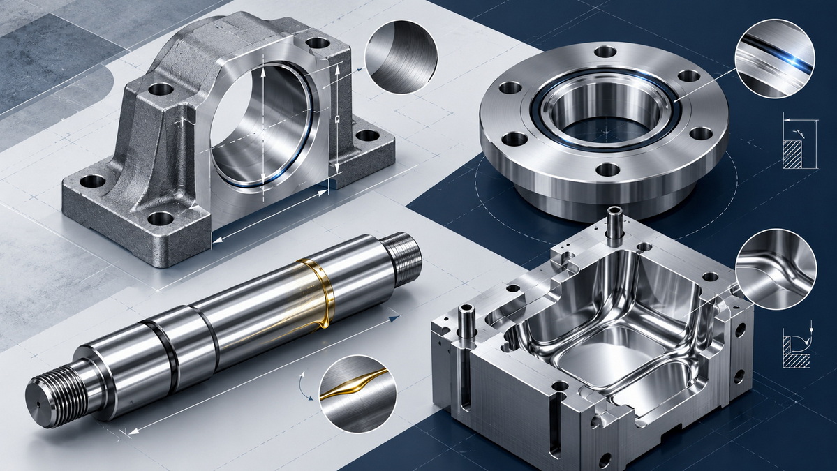
Many engineering drawings become expensive because they apply highly restrictive tolerances and fine surface finish requirements to all features.
This approach may appear safe, but it often creates unnecessary manufacturing complexity.
Over-specification can lead to:
- Higher machining cost
- Longer production lead time
- More setup operations
- Additional grinding or polishing
- More difficult inspection
- Higher rejection rates
- More expensive fixtures
- Lower production efficiency
- More limited supplier options
- Greater risk of inconsistent measurement results
For example, an external housing wall that is hidden inside an assembly may not need Ra 0.4 µm. If it does not seal, slide, carry a bearing, receive a special coating, or serve as a visible product surface, a standard machined finish may be fully acceptable.
Similarly, a non-mating wall of a machined aluminum housing may not need a ±0.01 mm tolerance. If the assembly allows more variation, a general tolerance can reduce cost and improve manufacturability without affecting performance.
Precision should be concentrated where it delivers functional value.
A structured engineering review can help teams decide where to prioritize tight tolerances, surface finish requirements, or both.
Before choosing a tolerance or roughness value, define what the feature must do.
Possible functions include:
- Locate another component
- Support a bearing
- Create a press fit
- Seal fluid or gas
- Guide movement
- Transfer load
- Retain lubricant
- Accept coating
- Provide a cosmetic surface
- Create a mold texture
- Release a molded part
- Mount an electrical connector
- Align an assembly
Start with function, not with a number.
Next, consider what could happen if the feature is not controlled correctly.
Typical failure modes include:
- Leakage
- Loose assembly
- Excessive interference
- Vibration
- Premature wear
- Galling
- Misalignment
- Corrosion
- Coating defects
- Cosmetic rejection
- Difficult assembly
- Fatigue cracking
- Mold flash
- Poor product release
The likely failure mode will reveal whether geometry, surface texture, or both are more important.
For tight tolerance features, a clear datum strategy is essential. Datums establish the reference surfaces or axes used to inspect the part.
Without a clear datum system, suppliers and inspectors may interpret feature location differently. This can create inconsistent inspection results, unexpected assembly issues, and disagreement during quality review.
A practical drawing should define the surfaces that control how the part sits, aligns, mounts, or mates with another component.
Avoid general notes such as "polish all surfaces" unless that is truly required.
Instead, define surface requirements for specific areas:
- Sealing faces
- Sliding surfaces
- Bearing contact surfaces
- Mold cavities
- Cosmetic faces
- Coated surfaces
- High-wear interfaces
- Fatigue-sensitive transitions
For critical features, specify the required roughness value, measurement direction, lay direction, allowable defects, and post-processing requirements.
Surface finishing processes can affect final dimensions. Grinding, polishing, lapping, blasting, anodizing, electroplating, powder coating, passivation, and heat treatment may all influence final size, surface condition, or edge geometry.
The manufacturing sequence should be planned carefully.
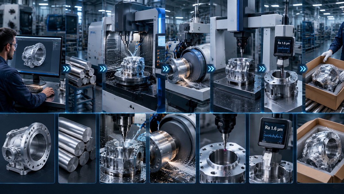
A common process route may include:
1. Material preparation
2. Rough machining
3. Stress relief or heat treatment
4. Semi-finish machining
5. Finish machining
6. Grinding, honing, polishing, or lapping
7. Surface treatment or coating
8. Dimensional inspection
9. Surface texture inspection
10. Final cleaning and packaging
A component should be evaluated as a complete manufacturing system, not as a collection of isolated drawing callouts.
A common assumption is that the smoothest possible surface always produces the best result. In real manufacturing, that is not always true.
Some applications need a controlled micro-texture to retain lubricant. A surface that is too smooth may reduce the ability of oil or grease to remain in the contact area. In other cases, aggressive polishing can soften critical edges, alter a profile, reduce dimensional accuracy, or create inconsistent appearance across multiple parts.
For molded products, a mirror-polished cavity may be ideal for transparent parts, high-gloss housings, lenses, and decorative components. However, a matte consumer product, leather-grain texture, anti-slip surface, or paint-ready housing may require a different mold texture and finishing method.
The right instruction is not "make it as smooth as possible."
The better instruction is: Create the surface condition that supports the part's intended function, material, assembly environment, and production process.
Mold manufacturing requires both high positional accuracy and controlled surface quality. Core and cavity inserts must align correctly to prevent flash, mismatch, and uneven parting lines.
At the same time, mold cavity finish affects:
- Product gloss
- Texture reproduction
- Mold release
- Ejection force
- Cleaning efficiency
- Scratch visibility
- Optical clarity
- Surface consistency of molded parts
Tight tolerances are important for insert alignment and shutoff areas. Surface finish is important for the cavity surfaces that transfer appearance and texture to the molded part.
Hydraulic manifolds, valve bodies, fittings, and pneumatic parts often require multiple control strategies.
Port positions, thread locations, and mounting holes may need tight dimensional tolerances. Sealing faces and valve interfaces may require controlled roughness, flatness, and burr removal.
A correctly positioned fitting can still leak if the contact face has deep grooves or uneven texture. A smooth face can still fail if the port is in the wrong location.
This makes hydraulic and pneumatic components a strong example of why feature-by-feature specification is essential.
In sheet metal fabrication, not every feature needs precision-machining-level tolerance.
Mounting holes, connector cutouts, folded flanges, hinge locations, and mating edges may need controlled dimensions and positions. However, wide exterior panels may require greater attention to:
- Scratch prevention
- Burr removal
- Grain direction
- Edge quality
- Welding marks
- Powder coating preparation
- Surface consistency
For visible enclosures, surface quality can strongly influence the perceived value of the finished product.
For custom precision parts, the correct balance depends on the part's role in the final assembly.
A simple bracket may need accurate holes and acceptable deburring. A pump shaft may need strict diameter control, runout control, and a fine surface finish. A mold insert may require tight positional tolerances, flatness, heat treatment, polishing, and texture preparation.
The key is to avoid using one general rule for all components. Each critical surface should be evaluated according to its function.
A well-prepared drawing and RFQ help manufacturers quote more accurately, identify risks earlier, and choose an efficient production route.
Include the following information whenever possible:
1. Material grade and condition
Identify the exact material, such as 6061-T6 aluminum, 7075 aluminum, SUS304 stainless steel, SUS316 stainless steel, POM, brass, titanium alloy, tool steel, or carbon steel.
2. Critical dimensions and geometric controls
Clearly mark dimensions that affect fit, alignment, sealing, movement, or assembly.
3. Surface finish requirements by functional area
Apply roughness requirements only to features that need them.
4. Post-processing requirements
State whether the part needs anodizing, electroplating, passivation, heat treatment, grinding, polishing, bead blasting, powder coating, laser marking, or other finishing processes.
5. Inspection requirements
Define whether the project requires first article inspection, dimensional reports, CMM reports, roughness testing, material certificates, coating thickness reports, or other quality documentation.
6. Production quantity
Prototype, low-volume, and mass-production requirements may need different tooling, machining strategies, and inspection plans.
7. Mating-part information
When possible, provide information about the mating component, especially for press fits, sealing interfaces, bearing fits, and moving assemblies.
Tight tolerance machining and surface finish requirements should not be viewed as competing priorities. They solve different engineering problems.
Tight tolerances protect fit, alignment, location, form, and assembly performance. They are essential for bearing seats, locating features, press-fit components, precision bores, mold inserts, and mating interfaces.
Surface finish requirements protect sealing, friction, wear, fatigue resistance, lubrication behavior, coating quality, cleanliness, and appearance. They are critical for sealing faces, sliding surfaces, cosmetic housings, mold cavities, fatigue-loaded components, and high-wear interfaces.
The most effective engineering approach is to evaluate every feature individually. Apply tight tolerances only where precision geometry controls function. Apply surface finish requirements only where surface condition affects performance or appearance. Use both where the component must achieve precise fit and controlled contact behavior at the same time.
For complex custom precision parts, molds, dies, and sheet metal components, early manufacturability review helps identify unnecessary cost, reduce drawing ambiguity, improve inspection consistency, and create a more reliable production process.
U-Need supports global customers with custom precision parts machining, injection mold manufacturing, stamping dies, cold-forging dies, and sheet metal fabrication. Sharing complete drawings, 3D models, material specifications, tolerance requirements, surface finish requirements, and expected order quantities allows the manufacturing process to be evaluated with greater accuracy from the beginning.
There is no single definition because tolerance capability depends on material, part size, geometry, machining process, machine condition, fixture design, and inspection method. In many projects, tolerances tighter than ±0.05 mm are treated as precision requirements. Tolerances around ±0.01 mm or tighter may require more controlled machining conditions and additional inspection.
No. Ra is widely used, but it does not fully describe all surface characteristics. Depending on the application, engineers may also need to evaluate Rz, Rq, waviness, material ratio, lay direction, peak height, valley depth, and visible surface defects.
In most cases, yes. Lower roughness values may require slower feed rates, additional finishing passes, sharper or specialized cutting tools, grinding, honing, lapping, polishing, and more inspection. The cost impact depends on the material, geometry, area to be finished, production quantity, and required process.
Yes. Polishing, grinding, lapping, blasting, plating, anodizing, coating, and heat treatment can affect dimensions, edge radii, surface texture, and final fit. Engineers should define whether dimensions apply before or after finishing and ensure that the process sequence is clear.
In many cases, yes. Flatness controls the overall contact condition across the sealing face. Roughness controls the smaller surface texture that can influence leakage paths, gasket compression, and contact behavior. The correct values depend on pressure, fluid type, gasket material, seal design, and mating-part condition.
Many general CNC-machined surfaces are specified around Ra 3.2 µm or Ra 1.6 µm. However, the right value depends on the part material, machining method, part function, mating surface, coating requirement, and acceptable cost. Fine grinding or polishing may be needed for more demanding surfaces.
Engineers can avoid over-specification by identifying the functional purpose of every feature. Apply strict tolerances only to dimensions that control fit, assembly, movement, sealing, or alignment. Use general tolerances for non-critical features. Apply fine surface finish only where it supports a functional or visual requirement.
1. ASME. [Surface Texture: ASME B46.1]
2. International Organization for Standardization. [ISO 21920-1:2021 — Geometrical Product Specifications (GPS) — Surface Texture: Profile — Part 1: Indication of Surface Texture]
3. International Organization for Standardization. [ISO 21920-2:2021 — Geometrical Product Specifications (GPS) — Surface Texture: Profile — Part 2: Terms, Definitions and Surface Texture Parameters]
4. International Organization for Standardization. [ISO 21920-3:2021 — Geometrical Product Specifications (GPS) — Surface Texture: Profile — Part 3: Specification Operators]
5. Physikalisch-Technische Bundesanstalt. [Standards in Roughness Measuring Techniques]
6. NASA Technical Reports Server. [Effect of Broaching Machining Parameters, Residual Stresses and Surface Roughness on Fatigue Life]
7. Venco MFG. [CNC Machining Tolerance Guide: ISO 2768 & GD&T]
8. Olympus Machining. [Surface Finish Requirements for Tight-Tolerance CNC Machining]


